

Description
- Model: IS230TNRLH1B
- Brand: General Electric (GE)
- Series: Mark VIe / Mark VIeS
- Part Type: Relay Output DIN-Rail Assembly
- Core Function: Provides a TMR discrete relay-output interface for Mark VIe turbine-control applications.
- Assembly Architecture: The TNRLH1B is reported as an assembly built around an IS200TRLYH1B terminal board with three PDOA I/O packs, matching its TMR architecture.
- Relay Configuration: Published technical information identifies 12 plug-in magnetic relays, with the first six configurable for dry Form-C contacts or external-solenoid drive; the remaining relay channels have specialized contact arrangements.
- Mounting: DIN-rail based, with conformally coated electronics reported for the H1B assembly.
- Warehouse Note: Verify the complete assembly before shipment. The market contains contradictory descriptions of this part number, including incorrect claims that it is a communication interface or generic 16-output module.
Product Introduction
In a turbine control cabinet, losing a relay-output assembly can affect multiple permissives, solenoids, shutdown commands, and auxiliary control circuits at once. The IS230TNRLH1B is designed for precisely this type of distributed Mark VIe relay-output service, with its TMR architecture providing three PDOA I/O packs around the relay terminal assembly.
The physical assembly is more than a single electronic card. Published technical records describe an IS200TRLYH1B terminal board plus three PDOA packs, with relay-contact and solenoid-excitation monitoring built into the architecture (a useful distinction when purchasing a New Surplus replacement).
Core Technical Specifications
| Parameter | Value |
|---|---|
| Manufacturer | General Electric |
| Model | IS230TNRLH1B |
| Series | Mark VIe / Mark VIeS |
| Functional Type | Relay Output DIN-Rail Module |
| Assembly Type | TMR relay-output assembly |
| Associated Terminal Board | IS200TRLYH1B |
| I/O Pack Architecture | 3 × PDOA I/O packs |
| Redundancy | TMR |
| Relay Count | 12 plug-in magnetic relays |
| Relay Configuration | First six configurable for dry Form-C or external-solenoid applications |
| Relay Channels 7–11 | Unpowered Form-C relay contacts |
| Relay 12 | Isolated Form-C contact for special applications |
| Monitoring | Hardware compatibility, relay-contact voltage, solenoid-excitation voltage |
| Mounting | DIN rail |
| PCB Coating | Conformal coating |
| Connector Locations | JR1, JS1, JT1 for the three I/O packs |
| Reported Maximum Inrush Current | 10 A |
| Approx. Commercial Unit Weight | 0.4–0.5 kg in some supplier records |
| Reported Packed Weight | Up to 1.5 kg in one commercial record |
| Reported Ambient Range | -40°C to +70°C in secondary listings |
| Exact Relay Contact Ratings | Must be verified against the specific terminal-board drawing and installed relay configuration |
The most important technical distinction is the 12-relay/TMR architecture. Do not replace it with a conventional single-pack discrete-output assembly simply because both parts are described as “relay output.”
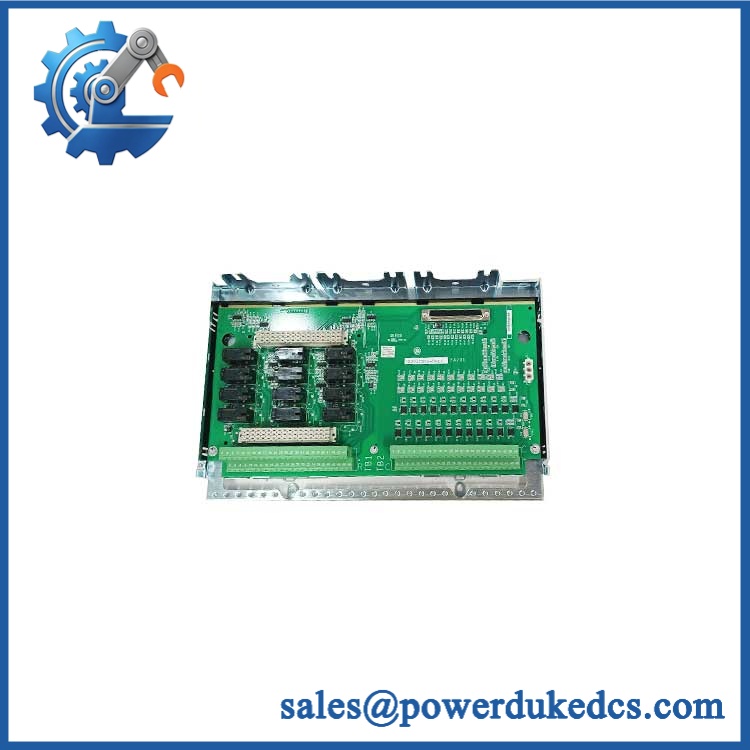
GE IS230TNRLH1B
Application Scenarios & Pain Points
For turbine auxiliary control, the assembly can serve relay-controlled field devices where multiple redundant output paths are required. The three-PDOA structure supports the TMR implementation documented for this assembly.
In an emergency shutdown or protective-control circuit, relay-contact supervision becomes a major maintenance concern. The reported diagnostics include relay-contact voltage and solenoid-excitation monitoring, allowing engineers to investigate a failed output path rather than relying only on a command-state indication.
At plants operating in 50°C+ cabinet environments, check the actual system thermal design before replacement. Secondary commercial sources cite a -40°C to +70°C range, but that should not override the GE-controlled environmental specification for the complete assembly.
During legacy Mark VIe maintenance, keeping one fully identified TNRLH1B assembly on the shelf can shorten an outage where several relay channels are tied to a common turbine subsystem.
With vs. without TMR: a standard single-output I/O assembly cannot reproduce the redundancy architecture of the TNRLH1B. Verify the control-system topology before authorizing a substitute.
Common Error Codes & Diagnostic Symptoms
Symptom/Code: Relay-contact voltage diagnostic active
→ Diagnosis: The expected relay contact voltage is absent or outside the configured range. Possible causes include relay failure, field wiring problems, fuse/open-circuit conditions, or a terminal-board issue. The TNRLH1B includes relay-contact voltage monitoring.
→ Action: Isolate the field circuit and verify relay, fuse, wiring, and terminal-board condition; replace the affected assembly when board-level failure is confirmed.
Symptom/Code: Solenoid excitation diagnostic active
→ Diagnosis: The monitored solenoid drive/excitation circuit is abnormal. Check external load, supply, wiring, and the relevant PDOA output path.
→ Action: Measure the field circuit under controlled conditions, then replace the failed I/O assembly if the output electronics are defective.
Symptom/Code: Hardware compatibility diagnostic / pack identification fault
→ Diagnosis: One or more installed PDOA packs, terminal-board hardware, or configuration records do not match the expected assembly architecture.
→ Action: Verify all three I/O packs and the IS200TRLYH1B terminal board against the approved Mark VIe configuration before replacing individual components.
GE public documentation reviewed for this part does not establish a universal numeric fault-code list. Use the site’s ControlST/ToolboxST diagnostic text and approved alarm database for exact code interpretation.
Cross-Reference & Lifecycle Migration
Assembly Identity
The strongest available identification is:
IS230TNRLH1B = Relay Output TMR DIN-Rail Assembly, Mark VIe, BPPC architecture.
Published technical records further describe the assembly as:
IS200TRLYH1B + 3 × PDOA I/O packs.
Related Models
GE’s Mark VIe catalog lists additional TNRL relay-output variants, including:
- IS230TNRLH1E
- IS230TNRLH1F
- IS230TNRLH2E
- IS230TNRLH2F
- IS230TNRLH3E
They are not automatically interchangeable with H1B. Different suffixes can represent different relay/output configurations, hardware populations, or application requirements.
Firmware and Configuration
The TNRLH1B uses a multi-pack Mark VIe architecture. Firmware compatibility should therefore be checked at the PDOA pack and Mark VIe software level, not merely at the DIN-rail assembly level. Do not flash firmware simply because another revision has a similar external appearance.
Lifecycle Status
Lifecycle classification: Legacy Mark VIe spare; current OEM status is not established from the reviewed public GE material.
For an operating turbine fleet, maintain a controlled spare where outage exposure is significant. Record the complete assembly number and the individual PDOA pack identities rather than storing the TNRLH1B only under a generic “relay output” description.
Field Engineer’s Tech Notes
Warning 1 — Do not replace one PDOA pack without checking the TMR architecture.
The is documented as a three-PDOA assembly. A technician who treats it like a standalone relay-output board can create an incomplete redundancy configuration or a hardware-identification fault.
Warning 2 — Do not trust generic relay ratings from third-party listings.
One commercial source incorrectly presents the part as a generic 16-channel output module with broad 24 VDC/120 VAC/240 VAC ratings, while more specific technical documentation identifies 12 magnetic relays and distinct relay-channel functions. Use the actual GE terminal-board/relay specification for load calculations.
Before installation, inspect JR1, JS1, and JT1 and the mating PDOA connectors for bent pins, oxidation, or mechanical damage.
Strict QA & Testing SOP
Step 1 — Inbound identity verification
Confirm GE IS230TNRLH1B against the purchase order. Capture photographs of every nameplate, assembly marking, serial number, and accessible PDOA pack identification.
Step 2 — Assembly completeness check
Verify the expected IS200TRLYH1B terminal board and three PDOA packs are present. Do not release an incomplete TMR assembly as a ready-to-install spare.
Step 3 — Physical inspection
Inspect the DIN-rail hardware, terminal connections, connectors JR1/JS1/JT1, relay sockets, fuses, PCB surfaces, and conformal coating.
Step 4 — Relay inspection
Check each installed magnetic relay for correct seating and visible damage. Confirm that the relay population matches the required configuration.
Step 5 — Controlled electrical test
Using an approved GE-compatible test fixture, verify the assembly’s power distribution and output behavior without exceeding the applicable relay-contact ratings.
Step 6 — Output-channel testing
Exercise each relay channel individually. Confirm commanded state, contact continuity, isolation behavior, and return-to-normal operation.
Step 7 — Diagnostic validation
Verify relay-contact monitoring, solenoid-excitation monitoring, and hardware-compatibility diagnostics where supported by the test environment.
Step 8 — TMR validation
Confirm that all three PDOA packs are recognized correctly by the Mark VIe configuration and that no hardware-identity fault is generated.
Step 9 — Final QA and packaging
Record serial numbers, test results, technician sign-off, inspection photographs, and configuration notes. Package the assembly in ESD-safe protective material with mechanical cushioning. Test videos are available with the QC record for procurement review.
Buyer’s FAQ
Q: Can I hot-swap the IS230TNRLH1B?
A: Do not assume it is safe to remove or replace under power. This assembly participates in a TMR relay-output architecture, and opening the relay-output path can create control or diagnostic consequences. Follow the plant’s approved Mark VIe maintenance procedure and verify the redundancy state before removal.
Q: How do I verify a New Original ?
A: Require photographs of the complete assembly, marking, terminal-board identification, three PDOA pack identities, serial/date information, and packaging. A box label alone is not sufficient evidence of authenticity.
Q: What is the correct replacement for an H1B?
A: Do not select H1E, H1F, H2E, H2F, or H3E solely because they are TNRL relay-output assemblies. GE’s catalog lists these as separate variants, and the exact relay/output architecture must match the installed system.
Q: What warranty should be required?
A: Require written coverage for DOA and functional failure, with serial-number traceability and a defined return/replacement process. For a TMR turbine-control assembly, the warranty should also cover the tested configuration supplied, not merely the outer DIN-rail hardware.











 Start Chat


