

Description
-
Model: IS410JPDHG1A
- Brand: GE General Electric
- Series: Mark VIe / Mark VIeS
- Part Type: JPDH High-Density Power Distribution Module
- Core Function: Distributes external 24/28 VDC control power across multiple protected branches feeding Mark VIe I/O packs and related field electronics. GE’s current hardware documentation identifies IS410JPDHG1A as a Mark VIe high-density control power distribution module.
- Key Specs: 22.5–28.6 VDC input, 13 A maximum input current, and 0.8 A maximum per output branch, with three groups of eight downstream branches for R/S/T distribution.
- Mounting: DIN-rail installation within the Mark VIe cabinet; this is a power-distribution device rather than an intelligent CPU or conventional I/O processor.
Product Introduction
Within a Mark VIe cabinet, loss of one control-power branch should not unnecessarily remove unrelated I/O packs. The GE IS410JPDHG1A addresses that physical distribution problem by dividing incoming DC control power into multiple downstream branches, allowing individual I/O loads to be supplied through separate protected paths rather than one common feed. GE documentation classifies it as a High Density Control Power Distribution module.
The electrical limits deserve close attention during cabinet design. The JPDH accepts 22.5 to 28.6 VDC, with 24/28 VDC nominal operation, a 13 A maximum input rating, and 0.8 A maximum per output channel; the documented architecture provides eight branch connections each for the R, S, and T rails. It is a passive distribution element, not a processor with application memory, firmware, or scan-time behavior (that distinction is important when the part appears in a PLC/DCS spare-parts database).
Core Technical Specifications
| Parameter | Value |
|---|---|
| Manufacturer | GE General Electric |
| Model | IS410JPDHG1A |
| Product Family | Mark VIe / Mark VIeS |
| Functional Group | JPDH High-Density Control Power Distribution |
| Part Type | DC Power Distribution Module |
| Input Voltage | 22.5–28.6 VDC |
| Nominal Input | 24.0 / 28.0 VDC |
| Maximum Input Current | 13 A DC |
| R-Rail Outputs | JR1–JR8 |
| S-Rail Outputs | JS1–JS8 |
| T-Rail Outputs | JT1–JT8 |
| Total Downstream Branches | 24 |
| Maximum Output Current | 0.8 A per branch |
| Output Voltage | Same as supplied DC input |
| Input Connectors | J1 and J1X |
| Mounting | DIN rail |
| Module Intelligence | Passive power-distribution hardware |
| Onboard Processor | None |
| Application Memory | None as a standalone distribution board |
| Communication Protocol | None |
| Associated Feedback Hardware | IS420PPDAH1B / applicable PPDA architecture |
| Operating Temperature | Up to +70°C in published commercial specifications |
| Hazardous-Area Status | Hazardous-location versions/configurations documented |
| Approx. Unit Weight | About 0.64 kg reported in commercial records |
| Estimated Shipping Size | About 16.5 × 15 × 11.5 cm reported for packed planning |
| Power Conversion | No AC-to-DC conversion; requires external DC source |
The 0.8 A branch limit is one of the most important field values. A downstream short should be isolated to its affected branch rather than allowed to consume the entire cabinet feed, provided the distribution architecture and upstream protection are correctly configured. GE’s equipment guide specifies the 13 A maximum input and 0.8 A maximum current for each JR/JS/JT output channel.
Heat calculations also need to be handled correctly. Because this is a power-distribution device rather than an active CPU module, there is no meaningful “memory limit” or scan-time specification; cabinet thermal evaluation should instead account for the module’s own electrical losses and the current carried by its 24 downstream branches.
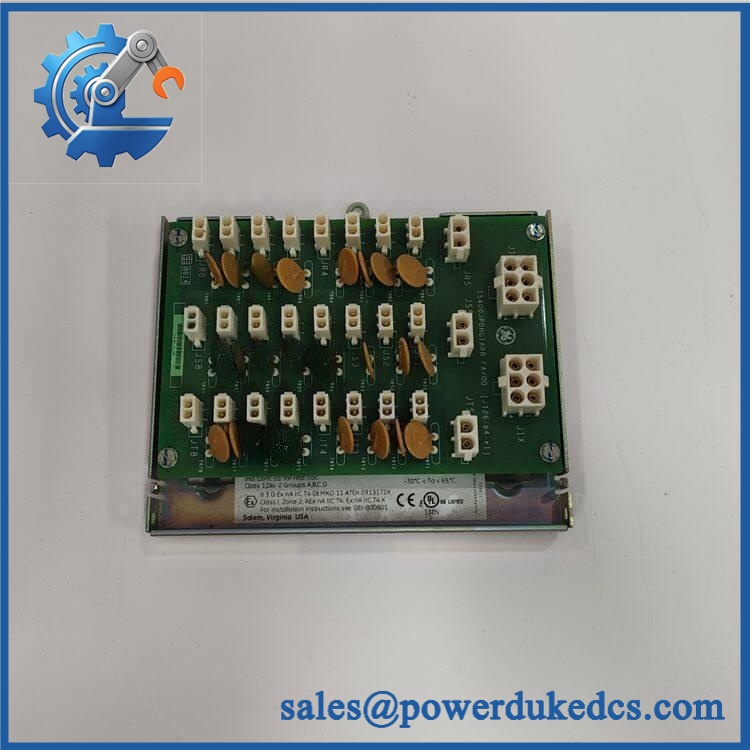
GE IS410JPDHG1A
Application Scenarios & Pain Points
At a gas-turbine site, the JPDH can distribute control power across multiple Mark VIe I/O loads. At elevated cabinet temperatures approaching 60°C, available current and conductor heating should be checked against the approved cabinet design rather than using a room-temperature assumption.
For triple-redundant turbine-control architectures, the separate JR, JS, and JT branch groups provide physical distribution for the corresponding control-power rails. A wiring mistake here can compromise the intended redundancy architecture even though every individual connection appears electrically energized.
In oil and gas compressor stations, hazardous-location certification can become the deciding procurement factor. GE documentation lists the IS410JPDHG1A among approved hazardous-location Mark VIe power-distribution modules, subject to the specified installation conditions.
With proper branch distribution, a failed downstream I/O load can be isolated to its assigned power path. Without correct branch assignment and upstream protection, a single wiring or load fault can create a much wider cabinet power disturbance.
For legacy migration, retaining the correct connector architecture is essential. Verify J1/J1X input wiring and JR/JS/JT branch assignments before replacing an older cabinet distribution assembly.
🚨 Common Error Codes & Diagnostic Symptoms
Symptom/Code: One I/O pack loses power while adjacent packs remain operational → Diagnosis: Suspect the corresponding JR/JS/JT output branch, connector seating, branch wiring, or downstream short circuit. → Action: Isolate the affected load, verify branch voltage/current, then replace the JPDH if the distribution hardware itself fails testing.
Symptom/Code: Several downstream I/O packs lose power simultaneously → Diagnosis: Check the incoming J1/J1X supply, upstream JPDS/JPDG distribution, and total source current before replacing individual I/O packs. → Action: Restore the common power path or replace the JPDH after proving an internal distribution fault.
Symptom/Code: R/S/T control-power redundancy imbalance → Diagnosis: Incorrect branch assignment, loose connection, or a failed distribution path can create an apparent redundancy problem. → Action: Compare every JR/JS/JT connection against the cabinet wiring drawing and test each rail independently.
The JPDH itself does not provide a processor-based fault-code system. Most diagnostic evidence appears at upstream feedback hardware, I/O-pack diagnostics, power measurements, or cabinet protection devices.
🚨 Cross-Reference & Lifecycle Migration
GE’s current Mark VIe/Mark VIeS equipment documentation identifies IS410JPDHG1A alongside IS210JPDHG1A and IS411JPDHG1A within the JPDH high-density power-distribution family. The document lists as Active, so it should not presently be classified as obsolete based on the available GE lifecycle table.
The IS411JPDHG1A is identified as the coated version in GE’s hardware documentation, while is the standard form. Do not treat that as a universal environmental substitution; coating, certification, and cabinet requirements must match the actual installation.
Lifecycle status: Active. For a critical Mark VIe installation, normal stocking can therefore follow installed-base risk and lead time rather than emergency hoarding. However, sites with obsolete upstream power-distribution hardware should retain at least one verified spare where a cabinet outage would affect multiple control nodes.
Firmware flashing is not applicable to the passive JPDH distribution module itself. If a replacement package includes an associated PPDA feedback device, that separate intelligent component must be evaluated for firmware and configuration compatibility.
Field Engineer’s Tech Notes
First warning: never size the incoming supply from the branch count alone. Twenty-four branches exist physically, but each is subject to its own 0.8 A maximum, while the JPDH input remains limited to 13 A. The actual cabinet load must be calculated from the connected equipment and redundancy arrangement.
Second warning: preserve the R/S/T wiring sequence. JR, JS, and JT are not interchangeable labels on a drawing. During replacement, photograph the existing conductors, verify every wire against the approved schematic, and confirm the rail assignment before applying power.
Also check the upstream supply. The JPDH does not convert AC to DC; an approved external DC power source is required, and hazardous-area installations impose additional source and enclosure requirements.
Strict QA & Testing SOP
Step 1 — Inbound inspection. Confirm , serial/date markings, revision, terminal labels, housing condition, DIN-rail latch, and connector condition. Photograph the entire assembly.
Step 2 — Mechanical inspection. Check the mounting clips, terminal hardware, connector retention, insulation, and board surfaces. Look for cracked plastic, overheated terminals, oxidation, or evidence of previous overcurrent.
Step 3 — Electrical verification. Apply a controlled DC source within the approved 22.5–28.6 VDC input range. Verify input current under the planned test load and confirm that output voltage tracks the supplied DC source.
Step 4 — Branch testing. Test JR1–JR8, JS1–JS8, and JT1–JT8 individually. Verify continuity, output voltage, connector integrity, and branch protection behavior using an approved test load rather than a direct short.
Step 5 — Load simulation. Apply representative I/O-pack loads and inspect voltage stability and localized heating. Monitor the module and terminals during a sustained load test.
Step 6 — Cabinet compatibility check. Confirm connector assignments, upstream JPDS/JPDG source, PPDA architecture where applicable, and the exact Mark VIe cabinet drawing before release.
Step 7 — Final QC. Record serial number, test readings, inspector, test date, and pass/fail status. Package the module in ESD-safe protective material and shield the connectors against impact.
Test videos are available for documented electrical and branch-output verification when a customer requires visual QC evidence.
Buyer’s FAQ
Treat it as an energized power-distribution component, not a routine hot-plug device. Removing it under load can interrupt multiple I/O branches and create electrical arcing or uncontrolled control-power changes; follow the approved cabinet isolation procedure before replacement.
How can I confirm a New Original unit is genuine?
Match the GE part number, serial/identification markings, revision, terminal layout, physical construction, and packaging. For critical procurement, request pre-shipment photographs and a documented incoming functional test rather than relying solely on the seller’s condition statement.
What warranty should be specified?
Put the coverage period and condition classification directly on the purchase order. The warranty should apply to the exact supplied, with clear terms for DOA, functional failure, and return handling.
Does this module come with the latest firmware pre-loaded?
No firmware should be expected on the JPDH itself. It is a passive power-distribution device; configuration and firmware concerns apply to associated intelligent Mark VIe components such as the PPDA or I/O packs, not to the JPDH power board.











 Start Chat


