

Description
- Model: GE IS410SRLYS2A
- Brand: General Electric
- Series: Mark VIeS Functional Safety System
- Part Type: SRLY Simplex Form-C Relay Output Terminal Board
- Core Function: Provides 12 isolated Form-C relay output circuits for the Mark VIeS discrete-output architecture, accepting one IS420YDOAS1B YDOA I/O pack.
- Key Specs: 12 relay outputs, 48 field terminals, simplex architecture, configurable contact-wetting/fusing through optional WRO-series daughterboards, DIN-rail mounting, 24/28 VDC I/O-pack control power, and IEC 61508 safety qualification.
Product Introduction
The GE IS410SRLYS2A sits at the field-wiring boundary of a Mark VIeS safety system. Unlike an active processor card, the SRLY is a simplex relay-output terminal board that mounts the YDOA I/O pack and distributes its twelve discrete commands through isolated Form-C relay contacts. Each relay also provides feedback to the I/O pack, allowing the control system to compare a commanded state with the resulting relay state.
For plant maintenance, the distinction between the terminal board and the YDOA pack is critical. The IS410SRLYS2A is the terminal assembly, while IS420YDOAS1B is the associated I/O pack ordered separately. Optional IS400WROBH1A, IS400WROFH1A, and IS400WROGH1A daughterboards add different contact-wetting and fuse arrangements (do not substitute one configuration for another without checking the field circuit).
Core Technical Specifications
| Parameter | Value |
|---|---|
| Manufacturer | GE General Electric |
| Model | IS410SRLYS2A |
| Series | Mark VIeS Functional Safety System |
| Functional Acronym | SRLY |
| Product Type | Simplex Form-C Relay Output Terminal Board |
| Architecture | Simplex |
| Compatible I/O Pack | IS420YDOAS1B |
| Number of Relay Outputs | 12 Form-C relay channels |
| Field Terminals | 48 customer terminals |
| Relay Contact Type | Form-C |
| Contact Rating | 0.6 A at 125 VDC |
| Contact Rating | 1.2 A at 48 VDC |
| Contact Rating | 2.25 A at 24 VDC |
| Contact Rating | 2.25 A at 120/240 VAC |
| Standard Contact Configuration | Dry contacts, no fuse |
| Relay Feedback | Isolated contact-pair feedback to YDOA |
| Output Line Monitoring | No |
| Sequence of Events | Configurable for relay feedbacks |
| Diagnostic Functions | Power-up self-test, I/O-pack health, command/feedback comparison, incorrect-terminal-board detection |
| WRO Daughterboards | IS400WROBH1A / IS400WROFH1A / IS400WROGH1A |
| Field Terminal Style | Pluggable Euro-style box terminal blocks |
| Supported Wire Size | Approximately 24 AWG to 12 AWG |
| I/O Pack Control Supply | 24/28 VDC |
| Maximum I/O Pack Power | 19.8 W, including relay-coil drive power |
| I/O Pack Power Connector | Micro Mate-N-Lok, AMP 1445022-3 |
| Physical Construction | Aluminum enclosure |
| Module Dimensions | 17.0 × 24.9 × 15.3 cm (H × W × D) |
| Mounting | DIN rail |
| Operating Temperature | -40°C to +70°C |
| Storage Temperature | -40°C to +85°C |
| Safety Rating | IEC 61508 compliant |
| Hazardous-Location Capability | Class I, Division 2 / Class II, Zone 2 / ATEX configuration |
| Life-Cycle Status | Active |
| Firmware on Terminal Board | None |
| Hot-Swap | Do not assume live replacement |
Contact-wetting configurations
The basic S2A board uses dry Form-C relay contacts. When a WRO daughterboard is installed, the same physical terminal assembly can provide controlled field-contact wetting and/or fuse monitoring.
The documented options have different purposes:
- IS400WROBH1A: Provides wetted and dual-fused distribution for selected relay circuits, with a dedicated arrangement for the final relay.
- IS400WROFH1A: Places one fuse in series with each relay common and provides fuse-voltage feedback.
- IS400WROGH1A: Provides individually fused powered outputs for all twelve relays.
The daughterboard therefore changes the field-power architecture. It should be treated as part of the ordered configuration, not as an interchangeable accessory.
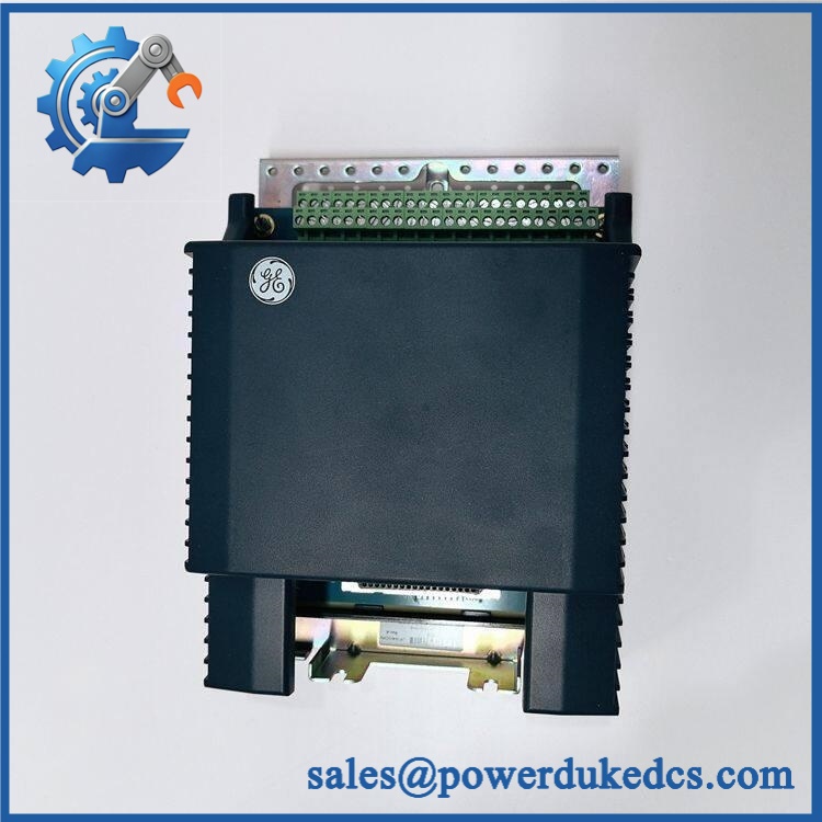
GE IS410SRLYS2A
Application Scenarios & Pain Points
Turbine shutdown interfaces: In a gas-turbine protection cabinet, the SRLY can route relay commands to solenoids, contactors, auxiliary relays, or other discrete field devices. The 12 Form-C channels provide both normally open and normally closed contact paths.
Generator and balance-of-plant systems: Relay outputs can interface with breaker-control or auxiliary equipment where galvanic separation between the I/O electronics and external circuits is required. The maximum contact rating reaches 2.25 A at 240 VAC under the specified conditions.
Safety-related auxiliary control: Because the S2A terminal-board configuration is designed for Mark VIeS functional safety applications, output feedback can be used to detect disagreement between an instructed relay state and the actual relay contact state.
Solenoid control: Where field loads need externally supplied wetting power and protection, an appropriate WRO daughterboard can add fused distribution. The exact daughterboard must match the load and field-power design.
High-temperature turbine enclosures: In cabinets operating around 60°C, relay coil heat, adjacent I/O packs, and enclosure ventilation all contribute to the local thermal condition. Do not evaluate the terminal board as an isolated heat source.
🚨 Common Error Codes & Diagnostic Symptoms
Symptom/Code: Commanded relay state does not agree with feedback
→ Diagnosis: The SRLY uses relay-contact feedback, so disagreement can result from a failed relay, damaged contact path, loose terminal wiring, or an external circuit problem.
→ Action: Verify the field circuit and feedback path first; replace the terminal-board assembly when controlled testing confirms relay hardware failure.
Symptom/Code: Incorrect terminal-board diagnostic
→ Diagnosis: The installed terminal-board identity or configuration does not match the I/O pack’s expected hardware arrangement.
→ Action: Confirm that the installed pack is IS420YDOAS1B and that the SRLY/daughterboard configuration matches the approved Mark VIeS system design.
Symptom/Code: Multiple relay outputs unavailable simultaneously
→ Diagnosis: A shared I/O-pack power issue, connector problem, YDOA fault, or common field-power problem is more likely than several independent relay failures occurring at once.
→ Action: Check the 24/28 VDC control supply, I/O-pack health, connector seating, and common wetting supply before replacing the SRLY.
The terminal board does not have a universal standalone numerical error-code table. Exact diagnostics are generated through the connected YDOA and Mark VIeS control environment.
🚨 Cross-Reference & Lifecycle Migration
Lifecycle Status: Active
Current GE Mark VIeS documentation identifies the IS410SRLYS2A as an active SRLY terminal board. The specified replacement I/O pack for this terminal-board configuration is IS420YDOAS1B, ordered separately.
Compatibility data
- IS410SRLYS2A: Simplex Form-C relay-output terminal board.
- IS420YDOAS1B: Current YDOA I/O pack specified for the S2A terminal board.
- IS400WROBH1A: Optional contact-wetting/fusing daughterboard.
- IS400WROFH1A: Optional per-relay-common fuse configuration.
- IS400WROGH1A: Optional twelve-channel single-fused output arrangement.
- TMR requirement: SRLYS2A is simplex. It should not be confused with the separate TRLY architecture used for TMR relay outputs.
- Firmware: No standalone firmware resides on the passive terminal board. Firmware applies to the connected YDOA I/O pack and Mark VIeS system.
- Migration: Replacing an older relay-output architecture with S2A/YDOA should be reviewed as a system configuration change, particularly where safety certification, wetting voltage, fuse monitoring, or TMR voting is involved.
For inventory planning, active status means routine replenishment remains possible, but safety-critical sites should still retain a verified spare because a terminal-board fault can interrupt an entire twelve-channel relay group.
Field Engineer’s Tech Notes
Warning 1 — Do not confuse SRLY with TRLY.
The . If the existing installation relies on 2oo3 relay voting, the correct terminal-board family is different. A physically compatible connector does not make the architecture equivalent.
Warning 2 — Record the WRO daughterboard before removal.
A replacement S2A without the original wetting/fusing arrangement can leave the relay contacts electrically functional while the field solenoids or powered loads remain unusable. Photograph the daughterboard type, fuse configuration, and all field connections before disconnecting the assembly.
Strict QA & Testing SOP
Step 1 — Inbound identity inspection
Verify , revision information, labels, serial/traceability data, enclosure condition, and the presence of the intended YDOA interface.
Step 2 — Daughterboard verification
Determine whether the unit is a basic dry-contact S2A or includes an IS400WROBH1A, IS400WROFH1A, or IS400WROGH1A option. Record the exact configuration.
Step 3 — Mechanical inspection
Check the DIN-rail mounting mechanism, aluminum enclosure, terminal blocks, relay interface, connector retention, and mounting hardware.
Step 4 — Continuity testing
Verify terminal-to-relay contact continuity using the approved schematic. Check normally open, normally closed, and common paths independently.
Step 5 — Relay functional testing
Operate all 12 relay channels through an approved YDOA-compatible test setup. Verify coil actuation, contact transition, and feedback response.
Step 6 — Contact-load testing
Where the test facility permits, exercise representative resistive loads within the specified relay ratings. Do not apply uncontrolled inductive loads merely to prove operation.
Step 7 — Wetting/fuse diagnostic testing
For WRO-equipped units, verify the applicable wetting-voltage distribution and fuse-monitoring functions. Record individual fuse channels where supported.
Step 8 — I/O-pack integration test
Install an approved test pack and confirm terminal-board recognition, health status, relay commands, and feedback diagnostics.
Step 9 — Documentation
Record relay-channel results, measured control power, daughterboard identity, terminal condition, serial number, photographs, and final QA status. Test videos are available as part of the QA evidence package when requested.
Step 10 — Final packaging
Use ESD protection for the YDOA interface, protect all terminal blocks and mounting hardware, apply the QC record, and package the assembly against impact and moisture during international transport.
Buyer’s FAQ — Dynamic Q&A
Q: Can the be hot-swapped?
A: Do not assume live replacement. The board carries relay circuits that may control external field loads, and the connected YDOA is part of a safety-system architecture. Follow the approved GE and site isolation procedure.
Q: What exactly is included when ordering ?
A: The . The specified YDOA pack, , is ordered separately. An optional WRO daughterboard may also be required depending on the field-contact wetting and fuse configuration.
Q: How do I verify a New Original unit?
A: Inspect the complete identification, revision, enclosure and terminal condition, relay arrangement, and any WRO daughterboard. For safety-controlled inventory, request serial/traceability information and a documented functional test rather than relying only on a visual inspection.
Q: What warranty should I require?
A: Require a written warranty tied to the exact supplied unit and tested configuration. The purchase record should identify the terminal-board revision, connected YDOA model where tested, daughterboard type if present, test results, serial/traceability information, and warranty start date.











 Start Chat


