

Description
- Model: IS410TRLYS1B
- Brand: General Electric (GE)
- Series: Mark VIeS Functional Safety System
- Part Type: TRLY Relay Output Terminal Board with Coil Sensing
- Core Function: Provides a 12-channel Form-C relay-output interface with relay-coil/feedback supervision for Mark VIeS discrete-output applications.
- I/O Pack: IS420YDOAS1B, ordered separately; one pack supports simplex operation while three packs support TMR architecture.
- Output Configuration: 12 Form-C relay channels; contacts 1–6 support wetted, dual-fused solenoid applications, while contacts 7–11 are dry Form-C and contact 12 has separate I/O wetting.
- Safety Classification: GE identifies the board as IEC 61508 compliant, with Class 1 Division 2, Class 2 Zone 2, and ATEX capability within the specified Mark VIeS configuration.
Product Introduction
The IS410TRLYS1B is installed on the field side of a Mark VIeS safety-control architecture, where it provides the relay interface between the IS420YDOAS1B discrete-output I/O pack and external field devices. It is not simply a passive terminal strip: the TRLYS1B architecture includes relay feedback and contact-wetting supervision, allowing the system to compare commanded output with the observed relay state.
For turbine safety applications, that distinction matters. The same terminal board supports simplex or TMR I/O-pack arrangements, with one or three YDOA packs respectively. The board is DIN-rail mounted and forms part of GE’s Mark VIeS safety-rated I/O architecture (a critical distinction from conventional Mark VIe relay boards).
Core Technical Specifications
| Parameter | Value |
|---|---|
| Manufacturer | General Electric |
| Model | IS410TRLYS1B |
| Series | Mark VIeS Functional Safety System |
| Functional Type | Relay Output with Coil Sensing |
| Terminal Board Function | Discrete relay output |
| I/O Pack | IS420YDOAS1B |
| I/O Pack Quantity | 1 for simplex / 3 for TMR |
| Relay Channels | 12 |
| Contact Type | Form-C |
| Digital Outputs | 12 DO |
| Contacts 1–6 | Wetted and dual fused for solenoid applications |
| Contacts 7–11 | Dry Form-C |
| Contact 12 | Separate I/O wetting |
| Contact Rating | 0.6 A @ 125 VDC; 1.2 A @ 48 VDC; 8 A @ 24 VDC; 3 A @ 120/240 VAC |
| Field Wiring | 24 AWG minimum to 12 AWG maximum |
| Terminal Blocks | Barrier-type |
| I/O Pack Control Supply | 24/28 VDC |
| Maximum I/O Pack Power | 19.8 W, including relay-coil drive |
| Diagnostics | Power-up self-test, I/O pack health, commanded-output vs. feedback comparison, loss of contact-wetting voltage, open-fuse detection, incorrect-terminal-board detection |
| SOE | Configurable for relay feedback |
| Output Line Monitoring | No |
| Safety Rating | IEC 61508 compliant |
| Hazardous-Location Capability | Class 1 Div. 2 / Class 2 Zone 2 / ATEX within specified configuration |
| G3 Environmental Compliance | Yes |
| Operating Temperature | -40°C to +70°C |
| Storage Temperature | -40°C to +85°C |
| Mounting | DIN rail |
| Complete Module Dimensions | 34.0 × 24.9 × 15.3 cm (H × W × D), including cover and I/O pack |
These specifications are from GE’s Mark VIeS technical documentation. The 12 Form-C relay channels, contact ratings, diagnostics, temperature limits, mounting method, and YDOA pack relationship are specifically identified there.
The important purchasing distinction is that IS410TRLYS1B is the terminal board, not the complete I/O pack. The associated IS420YDOAS1B must be ordered separately.
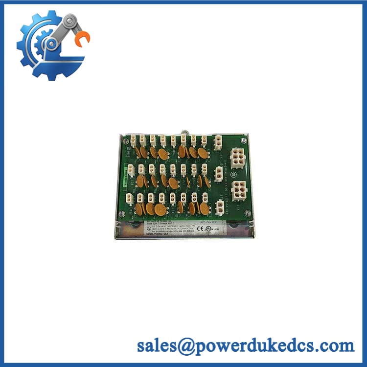
GE IS410TRLYS1B
Application Scenarios & Pain Points
In turbine auxiliary and safety-control circuits, the TRLYS1B provides relay contacts for field devices such as solenoids and other discrete actuators. Its 12-channel configuration is intended for applications where relay isolation and feedback supervision are required.
For a shutdown-related output that appears commanded but does not energize the field device, check contact-wetting voltage, fuse condition, relay feedback, and field wiring before replacing the YDOA pack. GE specifically lists these diagnostic functions for the S1B board.
At cabinet temperatures approaching 70°C, thermal assessment becomes part of the installation decision. GE specifies -40°C to +70°C operating temperature for the TRLYS1B arrangement, while storage is specified to +85°C.
During a Mark VIeS retrofit, do not substitute another TRLY suffix merely because the connector layout looks similar. GE distinguishes S1B, S1D, S1F, and S2F variants by relay architecture and diagnostic function.
With TMR enabled, three IS420YDOAS1B packs are mounted to the common terminal board. That architecture is materially different from a simplex installation using one I/O pack.
Common Error Codes & Diagnostic Symptoms
Symptom/Code: Incorrect Terminal Board Diagnostic
→ Diagnosis: The connected YDOA I/O pack detects a terminal-board identification mismatch or incompatible hardware configuration.
→ Action: Confirm the terminal-board identity, YDOA part number, hardware revision, and ControlST configuration before replacing hardware.
Symptom/Code: Commanded Output Does Not Match Relay Feedback
→ Diagnosis: The relay may have failed to transfer, the field circuit may be open, or the feedback/terminal circuit may be defective. GE explicitly identifies commanded-output versus feedback checking as part of the S1B diagnostic set.
→ Action: Check relay contacts, field wiring, fuses, and feedback circuitry; replace the defective board or I/O pack after isolation testing.
Symptom/Code: Loss of Contact-Wetting Voltage / Open Fuse Detection
→ Diagnosis: A loss of the required output-circuit wetting supply or an open fuse can prevent normal solenoid/relay operation.
→ Action: Verify the field power source and fuse circuits first; replace the terminal board only after external causes have been excluded.
GE’s public specification identifies diagnostic functions rather than providing one universal numeric alarm-code list for every Mark VIeS installation. The exact numeric fault displayed in ControlST depends on the configured system.
Cross-Reference & Lifecycle Migration
Current Part Identity
IS410TRLYS1B is the GE Mark VIeS Relay Output with Coil Sensing terminal board. GE currently lists its lifecycle status as Active.
Associated I/O Pack
The documented replacement/associated I/O pack is:
IS410TRLYS1B → IS420YDOAS1B
The YDOA is a separate orderable component. One pack is used for simplex operation; three are used for TMR.
Related TRLY Variants
Do not automatically cross-reference the following:
- IS410TRLYS1D — Relay Output with Solenoid Integrity Sensing
- IS410TRLYS1F — TMR Contact Voting, Form-A version
- IS410TRLYS2F — TMR Contact Voting, Form-B version
These variants have materially different relay functions. For example, S1D uses six normally open relays with load-integrity monitoring, while S1F and S2F use TMR-voted Form-A or Form-B contacts.
Firmware Consideration
The terminal board itself does not carry the application firmware. Firmware resides in the associated . GE’s certification material specifies minimum software versions for Mark VIeS hardware combinations; therefore, verify the actual YDOA firmware and ControlST baseline when replacing a complete assembly.
Lifecycle Stock Strategy
Status: Active.
For a running Mark VIeS turbine, maintain the board as a controlled spare where relay-output failure could affect the safety function. Inventory records should distinguish the IS410TRLYS1B terminal board from the so that a partial assembly is not mistakenly treated as a complete replacement.
Field Engineer’s Tech Notes
Warning 1 — Do not confuse coil sensing with solenoid integrity sensing.
The S1B and S1D are different designs. S1B provides relay-coil/feedback supervision and contact-wetting/open-fuse diagnostics, whereas S1D adds dedicated solenoid-integrity sensing. Selecting S1D as a casual substitute can change the diagnostic behavior expected by the safety application.
Warning 2 — Respect the relay load rating by voltage.
The permissible contact current is not one universal number. GE specifies 8 A at 24 VDC, but only 0.6 A at 125 VDC, with separate AC ratings. A relay suitable for a low-voltage DC solenoid is not automatically suitable for a higher-voltage DC load.
For field replacement, also inspect the barrier terminal blocks and relay wiring for heat discoloration. A failed relay may be the symptom of an overloaded or inductive field circuit rather than the original cause.
Strict QA & Testing SOP
Step 1 — Inbound identity check
Verify against the purchase order, including serial/date information and hardware markings. Photograph the nameplate before inventory acceptance.
Step 2 — Assembly verification
Determine whether the shipment contains the terminal board alone or the complete board plus pack. Record the two items separately in the asset register.
Step 3 — Physical inspection
Inspect the DIN-rail mechanism, barrier terminal blocks, relay sockets, connectors, fuses, PCB surfaces, and protective cover. Look for corrosion, cracked housings, loose hardware, and thermal discoloration.
Step 4 — Relay verification
Confirm the relay population and channel identification. Check that contacts 1–6, 7–11, and 12 correspond to the documented configurations.
Step 5 — Controlled power test
Use an approved Mark VIeS test fixture and verify the associated YDOA power input and startup behavior. Do not exceed the documented 19.8 W maximum I/O-pack power.
Step 6 — Output-channel test
Exercise each relay output individually. Verify Form-C contact transfer, contact resistance, and correct terminal mapping.
Step 7 — Diagnostic test
Test the supported feedback functions, including commanded-output versus relay feedback, wetting-voltage monitoring, fuse-status diagnostics, and incorrect-terminal-board detection.
Step 8 — Mark VIeS configuration test
Connect the YDOA to an approved test environment and verify hardware identification, I/O health, and the applicable simplex or TMR configuration.
Step 9 — Final QA and packaging
Record channel-by-channel results, serial numbers, photographs, inspection date, and technician sign-off. Package the board using ESD-safe materials with adequate mechanical protection. Test videos are available with the QC record when required for procurement verification.
Buyer’s FAQ
A: Do not assume live replacement is permitted. The board is part of a Mark VIeS safety-rated relay-output architecture, and removing it can affect field outputs or the validated safety function. Follow the site-approved maintenance procedure and establish the required safe state before disconnection.
Q: Is the supplied with the YDOA I/O pack?
A: Not automatically. GE lists as the associated I/O pack and states that it is ordered separately. A terminal-board-only shipment should not be recorded as a complete I/O module.
Q: Is the still an active GE part?
A: Yes. GE’s Mark VIeS technical specification currently lists .
Q: What should I require for a New Original unit and warranty?
A: Require clear nameplate photographs, full part-number verification, serial/date traceability, country-of-origin documentation, and a functional test report. Warranty terms should cover DOA and functional failure and identify the return/replacement process by serial number.











 Start Chat


