

Description
- Model: GE IS420UCSBH1A
- Brand: General Electric
- Series: Mark VIe / EX2100e / LS2100e
- Part Type: UCSB Standalone Controller Module
- Core Function: Executes the turbine or excitation-control application and communicates with distributed Mark VIe I/O over GE’s dedicated IONet architecture.
- Key Specs: 600 MHz Intel EP80579 processor, 256 MB DDR2 ECC SDRAM, 2 GB NAND flash, QNX Neutrino RTOS, three IONet Ethernet interfaces plus ENET1/ENET2, 27.4–28.6 VDC, and approximately 15.6 W nominal / 26.7 W peak power consumption.
- Lifecycle Position: Legacy/discontinued in current distribution channels, making verified replacement stock important for operating installations.
Product Introduction
The IS420UCSBH1A is mounted directly to the control-panel structure and functions as a standalone computer rather than a backplane CPU. Application code runs locally on the UCSB, while process I/O remains distributed across the dedicated IONet network. Three Ethernet ports provide the R, S, and T I/O-network connections, while ENET1 and ENET2 serve controller-level communication functions.
Hardware resources are substantial for this older generation: a 600 MHz Intel EP80579, 256 MB ECC DDR2 SDRAM, flash-backed SRAM, and 2 GB NAND flash. QNX Neutrino provides the real-time operating environment. The controller is fanless and battery-free, and GE states that its flash memory can be updated through the controller’s service functions.
Core Technical Specifications
| Parameter | Value |
|---|---|
| Manufacturer | GE General Electric |
| Model | IS420UCSBH1A |
| Functional Acronym | UCSB |
| Product Type | Standalone Controller Module |
| Supported Platforms | Mark VIe, EX2100e, LS2100e |
| Processor | Intel EP80579, 600 MHz |
| Main Memory | 256 MB DDR2 SDRAM with ECC |
| NAND Flash | 2 GB |
| SRAM | Flash-backed SRAM |
| Nonvolatile Memory | NVRAM |
| Operating System | QNX Neutrino |
| Programming | Control block language; Boolean logic represented in relay-ladder format |
| IONet Interfaces | 3 × 10/100Base-TX RJ-45 |
| ENET1 | 10/100Base-TX RJ-45; UDH / controller communications |
| ENET2 | 10/100Base-TX RJ-45; Ethernet Modbus, OPC UA, or CDH on supported Mark VIe configurations |
| Service Interface | COM1 configuration interface; USB service connection |
| Power Input | 27.4–28.6 VDC |
| Nominal Voltage | 28.0 VDC |
| Maximum Current | 1.1 A DC |
| Nominal Power | 15.6 W |
| Peak Power | 26.7 W |
| Mounting | Direct panel mounting |
| Cooling | Fanless |
| Battery | None |
| Storage Temperature | -40°C to +85°C |
| Operating Ambient | -30°C to +65°C |
| Approx. Dimensions | 8.011 × 6.313 × 1.044 in. / 203.5 × 160.4 × 26.5 mm |
| Approx. Weight | 1.0 kg / 2.4 lb |
| Firmware | Application-specific |
| Hot Replacement | Do not assume live replacement |
GE’s general-purpose UCSB documentation gives the 15.6 W nominal and 26.7 W peak figures and identifies the 1 kg class weight and -30°C to +65°C ambient rating. GE’s hazardous-location equipment guide specifies the tighter 27.4–28.6 VDC input range and 1.1 A maximum current for the UCSB controller.
Network architecture
The three IONet ports are not generic Ethernet ports. They form GE’s dedicated real-time controller-to-I/O network, with the R, S, and T physical network arrangement corresponding to the controller’s redundancy architecture. ENET1 and ENET2 serve separate higher-level communication roles; in particular, ENET2 is not supported for Mark VIeS Safety control.
The controller also carries application-specific software. A replacement UCSBH1A therefore requires more than matching the processor and memory; IP addressing, application image, ControlST compatibility, I/O network configuration, and system backup data must be reconciled before startup.
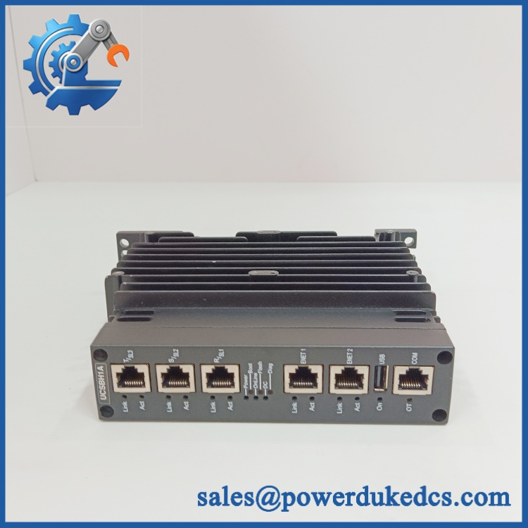
GE IS420UCSBH1A
Application Scenarios & Pain Points
Gas-turbine main control: The UCSBH1A can execute the application code responsible for turbine sequencing, control logic, alarms, and distributed-I/O processing. Three IONet interfaces allow the controller to participate in simplex, dual, or TMR system architectures.
EX2100e excitation: The same controller hardware family is identified by GE for EX2100e applications. That makes configuration identity particularly important: a controller removed from one application should not be loaded into another simply because the hardware label matches.
LS2100e static starter: The UCSBH1A is also listed for LS2100e use. Application software and I/O assignments remain system-specific.
Brownfield controller replacement: In an aging Mark VIe installation, a failed CPU can produce a plant-wide control outage even while every distributed I/O pack remains powered. Maintaining a tested spare with a verified application backup can materially reduce recovery time.
High-temperature control cabinets: At 50°C+ ambient, cabinet airflow around the controller’s vertical cooling fins deserves attention. GE specifies unobstructed airflow through those fins, so adjacent wiring ducts or newly installed hardware should not block the thermal path.
🚨 Common Error Codes & Diagnostic Symptoms
Symptom/Code: Controller not visible on one or more IONet paths
→ Diagnosis: Possible loss of the corresponding Ethernet link, incorrect network cabling, controller configuration problem, or controller-side network hardware fault. Because the three IONet ports correspond to the distributed I/O architecture, inspect the affected path before replacing every connected I/O module.
→ Action: Check link/activity indicators, cable routing, network switch status, controller configuration, and then substitute a verified UCSBH1A if hardware failure is confirmed.
Symptom/Code: Controller boots but application does not reach the expected running state
→ Diagnosis: The hardware may be healthy while the application image, IP configuration, ControlST revision, or stored program image is incorrect. The UCSB runs application-specific software from its nonvolatile storage.
→ Action: Compare the controller backup with the approved site image and restore the correct application before condemning the hardware.
Symptom/Code: Repeated reboot / unstable controller startup
→ Diagnosis: Check the DC source first. The UCSBH1A is specified for 27.4–28.6 VDC, and an inadequate supply can produce behavior that resembles processor or NAND-flash failure.
→ Action: Measure the supply at the controller connector under load; replace the controller only after the power source and wiring are proven acceptable.
Exact numerical fault identifiers vary by Mark VIe application and software revision. Use the installed ControlST diagnostic record as the authority.
🚨 Cross-Reference & Lifecycle Migration
Lifecycle Status: Legacy / Discontinued
Current distributor records identify IS420UCSBH1A as discontinued, while GE technical and certification documentation continues to identify the part as a UCSB controller. For an installed asset, that combination means the hardware remains technically documented but should be treated as a legacy spare rather than normal new-production replenishment.
Critical compatibility data
- IS420UCSBH1A: 600 MHz EP80579 UCSB controller.
- IS420UCSBH4A: Later UCSB hardware using a 1066 MHz EP80579. It should not be treated as an unconditional drop-in replacement merely because the mechanical envelope is similar.
- IS420UCSBH3A: Another UCSB generation using a 1200 MHz EP80579; its thermal and power characteristics differ from H1A.
- IS421UCSBH1A: Conformal-coated counterpart documented by GE for applicable environments. Do not substitute it without checking the environmental and certification requirements.
- IS420UCSBS1A: Mark VIeS Safety controller. It is not the same controller application as the standard UCSBH1A; the H1A is identified for Mark VIe, EX2100e, and LS2100e.
- Firmware flashing: The UCSB flash memory can be updated, but firmware flashing does not make different UCSB hardware generations electrically or functionally identical. The application image, ControlST version, configuration, and controller revision must be reviewed together.
- Buffer-stock strategy: Because H1A is discontinued in current distribution records, keep at least one tested spare for each critical installed controller architecture rather than relying on emergency aftermarket availability.
Field Engineer’s Tech Notes
Warning 1 — Back up the application before touching the replacement.
This is a standalone computer, not a passive I/O board. The replacement controller needs the correct application, network identity, and site configuration. A powered-up controller with the wrong image can look like a hardware failure when the real problem is configuration.
Warning 2 — Do not block the cooling fins.
The H1A is fanless. GE’s installation drawing specifically calls for unobstructed vertical airflow through the fins. Cable bundles, labels, or cabinet additions placed directly against that path can raise internal temperature even when the cabinet itself appears acceptable.
Strict QA & Testing SOP
Step 1 — Inbound identity inspection
Verify IS420UCSBH1A, hardware revision, serial number, manufacturing label, connector condition, enclosure condition, and any evidence of previous repair.
Step 2 — Mechanical inspection
Confirm the direct-panel mounting arrangement, mounting holes, connector retention, cooling-fin condition, and physical envelope.
Step 3 — Electrical pre-check
Check the power input for abnormal resistance or contamination. Verify the test supply can maintain 27.4–28.6 VDC under load.
Step 4 — Controlled power-up
Power the controller on an approved test fixture and record startup behavior, status LEDs, boot behavior, supply voltage, and current.
Step 5 — Memory and storage verification
Verify the controller identifies its 256 MB ECC memory and 2 GB NAND flash correctly. Check that the flash storage is accessible and does not exhibit repeated boot or filesystem errors.
Step 6 — Ethernet interface testing
Test all three IONet ports individually, followed by ENET1 and ENET2 where applicable. Confirm link stability, packet exchange, and correct interface assignment.
Step 7 — Application restore test
Load the approved test application or site-authorized backup and confirm that the controller reaches the expected running state without configuration faults.
Step 8 — I/O communication test
Connect a representative Mark VIe I/O network and verify communication with selected I/O packs. For redundant systems, test the applicable R/S/T network paths independently.
Step 9 — Configuration verification
Record firmware/software revision, IP configuration, application image, hardware revision, and controller identification. Confirm that the replacement matches the site’s approved baseline.
Step 10 — QA evidence and packaging
Record measured supply voltage, current, boot results, Ethernet test results, application test results, serial number, and inspection photographs. Test videos are available as part of the QA evidence package when requested. Package the controller in ESD protection with the connectors mechanically protected.
Buyer’s FAQ — Dynamic Q&A
Q: Can the be hot-swapped?
A: Do not assume it. Although GE’s distributed architecture is designed to reduce loss of application input during controller maintenance in redundant configurations, physical replacement must follow the approved Mark VIe maintenance procedure and the actual simplex, dual, or TMR architecture.
Q: How do I verify a “New Original” ?
A: Verify the full catalog number, hardware revision, serial/traceability markings, enclosure and connector condition, and application-specific QA report. A clean-looking surplus controller is not equivalent to documented New Original OEM stock.
Q: Does a replacement controller need firmware or application loading?
A: Usually, the application image and configuration must be verified because the UCSB runs application-specific software. The flash memory is updateable, but simply flashing a newer image does not guarantee compatibility with the existing ControlST baseline or turbine application.
Q: What warranty should I require for this discontinued controller?
A: Require a written warranty tied to the exact serialized controller and its tested condition. For a critical controller spare, the purchase file should include the hardware revision, power-up test, memory/storage verification, Ethernet test results, application-load verification, serial number, and warranty start date.











 Start Chat


