

Description
- Model: IS420UCSBH3A
- Brand: General Electric (GE)
- Series: Mark VIe / MarkStat
- Part Type: UCSB Controller Module
- Core Function: Executes Mark VIe control applications and exchanges real-time control data with distributed I/O packs across the controller network. GE documentation identifies the H3A specifically as a Mark VIe or MarkStat controller.
- Processor: 1200 MHz Intel EP80579
- Memory: 256 MB DDR2 SDRAM with ECC plus 2 GB NAND flash reported in technical records.
- Network Architecture: Three IONet paths are used for R/S/T controller-to-I/O communications; the UCSB also belongs to a controller family supporting simplex, dual, and TMR system configurations.
- Power: Approximately 17.3 W nominal / 28.7 W peak in supplier technical data.
- Environmental Range: 0°C to +65°C for the IS420UCSBH3A in GE’s hazardous-location certification documentation.
Product Introduction
In the Mark VIe architecture, the IS420UCSBH3A is the controller rather than an individual field I/O module. It executes the control application, processes data received from the distributed I/O network, and distributes control commands to connected I/O packs. GE’s documentation identifies this exact model as a UCSB Mark VIe or MarkStat controller, built around a 1200 MHz Intel EP80579 processor.
From a lifecycle-management perspective, this hardware is a significant controller-generation reference. The UCSB family includes older H1A, H4A, and newer controller families, but the H3A should not be treated as a generic replacement for every UCSB revision. Software baseline, application image, network architecture, and controller redundancy all need validation before a legacy migration or New Surplus replacement is released to the plant.
Core Technical Specifications
| Parameter | Value |
|---|---|
| Manufacturer | General Electric |
| Model | IS420UCSBH3A |
| Functional Abbreviation | UCSB |
| Platform | GE Mark VIe / MarkStat |
| Controller Type | Mark VIe Controller |
| Processor | Intel EP80579 |
| Processor Speed | 1200 MHz |
| CPU Architecture | Quad-core is reported in commercial technical documentation |
| System Memory | 256 MB DDR2 SDRAM, ECC |
| Application Storage | 2 GB NAND flash |
| Operating System | QNX Neutrino RTOS |
| I/O Network | GE IONet |
| IONet Configuration | R / S / T network architecture in TMR systems |
| Ethernet | Controller/network Ethernet interfaces; exact port assignment depends on system architecture |
| Input Supply | 24/28 VDC nominal; supplier data reports 18–36 VDC input range |
| Nominal Power | Approx. 17.3 W |
| Peak Power | Approx. 28.7 W |
| Operating Temperature | 0°C to +65°C |
| Storage Temperature | Up to +85°C reported commercially |
| Approx. Dimensions | 6.4 × 8.1 × 1.4 in (H × W × D) |
| Approx. Weight | 2.9 lb / 1.3 kg |
| Mounting | Panel / sheet-metal mounting |
| Controller Role | Real-time Mark VIe application execution and I/O coordination |
The 1200 MHz EP80579, Mark VIe/MarkStat designation, and 0°C to +65°C hazardous-location temperature envelope are supported by GE-related documentation. Supplier records provide the memory, power, dimensions, and weight figures above; those mechanical and power values should be reconciled with the site drawing before formal cabinet calculations.
A particularly important distinction is that the H3A is not a conventional VME plug-in controller. It is a UCSB module installed at the panel level and communicates with distributed I/O over the Mark VIe network architecture.
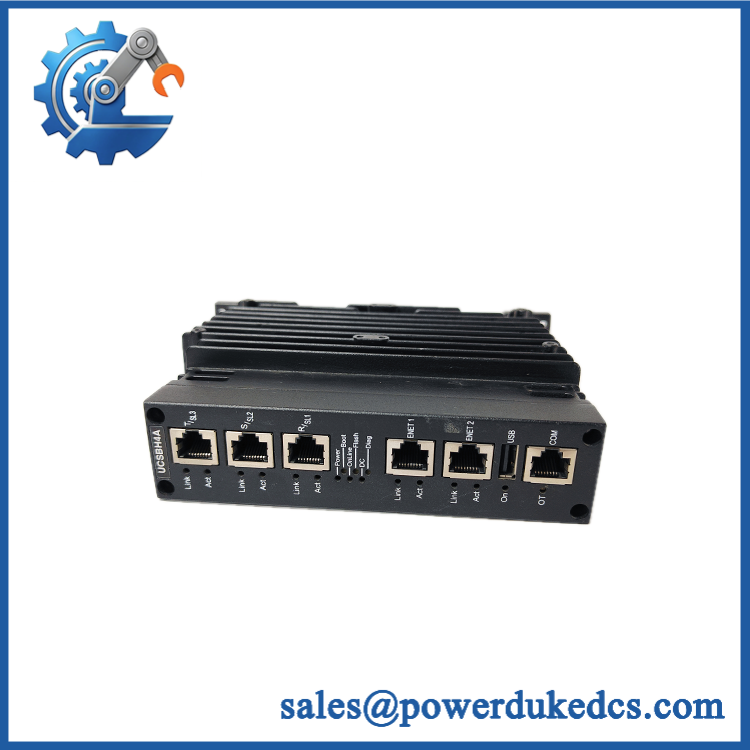
- GE IS420UCSBH3A
Application Scenarios & Pain Points
During a gas-turbine startup, controller processing latency becomes a direct operational concern. The UCSBH3A provides the real-time computation layer for the Mark VIe application while the I/O packs handle field acquisition and output execution.
For TMR turbine-control architectures, the controller participates in the three-controller / three-I/O-network arrangement. GE’s marine type-approval documentation lists the UCSBH3A among supported Mark VIe controller processors and explicitly describes simplex, dual, and TMR controller configurations.
At a cabinet operating near 60°C, the temperature margin deserves attention because the certified ambient range for this exact model is 0°C to +65°C. A failed cabinet fan or rising enclosure temperature should be investigated rather than simply replacing the controller.
During legacy controller replacement, memory and application-image handling become the practical pain points. A replacement with the correct external part number can still require configuration and software-image verification before it can assume the original controller’s role.
In an industrial power-generation environment, maintaining one tested spare avoids turning a controller fault into a longer outage caused by sourcing, configuration recovery, and FAT/SAT retesting.
Common Error Codes & Diagnostic Symptoms
Symptom/Code: ONLINE indicator does not reach the expected state
→ Diagnosis: Possible application-image, controller startup, network, power, or hardware fault. The UCSB front panel includes multiple status indicators intended to separate startup, online, flash, DC, diagnostic, and network conditions.
→ Action: Check DC supply, startup indicators, controller diagnostics, and network connectivity before condemning the module.
Symptom/Code: OT / over-temperature indication
→ Diagnosis: Excessive controller temperature may be caused by cabinet ambient conditions, blocked airflow, fan problems, or an internal thermal fault. Commercial technical records specifically identify an OT LED for over-temperature indication.
→ Action: Correct the thermal condition and confirm controller health; replace the UCSBH3A when the hardware is verified as the failed element.
Symptom/Code: IONet communication loss / repeated link or ACT faults
→ Diagnosis: Possible Ethernet cabling, switch/network, power, controller-interface, or IONet configuration problem. The H3A relies on the Mark VIe IONet architecture for communication with distributed I/O.
→ Action: Test each network path systematically and compare controller diagnostics with a known-good configuration.
GE’s public documentation reviewed here does not establish one universal numeric alarm-code table for every IS420UCSBH3A installation. Use the actual ControlST diagnostic message and site alarm database for exact code interpretation.
Cross-Reference & Lifecycle Migration
Controller Family
GE’s controller documentation identifies the following related UCSB generations:
- IS420UCSBH1A — 600 MHz EP80579
- — 1200 MHz EP80579
- IS420UCSBH4A — 1066 MHz
- IS420UCSBS1A — Mark VIeS Safety Controller generation
The H3A is therefore not interchangeable solely because all four models use the UCSB designation. Processor generation, application support, and safety role differ.
H3A System Role
= Mark VIe / MarkStat controller.
GE’s hazardous-location documentation lists it specifically under the Mark VIe controller family, rather than the Mark VIeS Safety Controller category.
Firmware / Application Image
The controller runs the QNX Neutrino operating system and stores application software in NAND flash. Replacement planning therefore has two separate checkpoints:
- Hardware identity and controller compatibility.
- Approved Mark VIe application/software image.
Do not assume that a New Original controller contains the same application image, revision, configuration, or site-specific control database used by the removed unit.
Lifecycle Status
Lifecycle classification: Mature / legacy-support asset; current OEM commercial lifecycle status is not conclusively established from the public sources reviewed.
The model remains explicitly listed in GE certification and technical documents, including a 2026 Intertek constructional-data report for GE VERNOVA low-voltage I/O and communication controls. That confirms the model remains within documented equipment scope, but it does not by itself establish unrestricted current production availability.
For inventory strategy, sites still dependent on Mark VIe H3A controllers should maintain a tested spare and preserve the approved controller software image separately.
Field Engineer’s Tech Notes
Warning 1 — Do not confuse a controller swap with a logic restore.
A physically correct does not guarantee that the plant can resume control immediately. Preserve the existing application configuration and software baseline before removing a failed controller. The controller contains the computational platform; the site-specific application is a separate asset-management concern.
Warning 2 — Treat the 0°C lower temperature limit seriously.
Unlike several other Mark VIe modules with wider environmental ranges, the certification documentation specifically places the H3A at 0°C to +65°C. Cold outdoor cabinets, HVAC failures, or unconditioned enclosures can therefore move this controller outside its documented operating envelope.
One more practical check: inspect the controller’s mounting and airflow arrangement. The module is panel-mounted, so loose hardware or cabinet vibration can create problems that look like network faults later.
Strict QA & Testing SOP
Step 1 — Inbound identity inspection
Verify the complete marking and record serial number, hardware revision, date code, and packaging identifiers. Photograph the label before acceptance.
Step 2 — Physical inspection
Check the enclosure, mounting points, Ethernet connectors, indicator panel, ventilation path, and accessible PCB areas for damage, corrosion, contamination, or evidence of previous overheating.
Step 3 — Documentation reconciliation
Confirm processor generation, memory configuration, hardware revision, and applicable Mark VIe compatibility before the unit enters available inventory.
Step 4 — Controlled power test
Use an approved test fixture and regulated DC supply. Monitor startup behavior, DC indication, boot sequence, diagnostic status, and current draw. Do not use an uncontrolled bench supply.
Step 5 — Controller self-test
Verify startup completion, processor operation, memory checks, flash access, and expected diagnostic state.
Step 6 — Network test
Connect the controller to an approved Mark VIe test environment and verify the expected IONet/controller communications. Exercise the applicable R/S/T paths independently where the test architecture permits.
Step 7 — Application-image verification
Confirm that the controller accepts the approved software/application image and that the installed baseline is suitable for the intended site. Record version data rather than relying on a generic “firmware loaded” label.
Step 8 — Thermal observation
Operate the controller under controlled load while monitoring temperature behavior. The certified operating ceiling is +65°C, so abnormal heating should trigger investigation before release.
Step 9 — Final QA and packaging
Record all test values, serial number, firmware/software identification, inspection photographs, and technician sign-off. Package the controller in ESD-safe material with mechanical cushioning. Test videos are available with the QC record for procurement review.
Buyer’s FAQ
A: Do not assume live replacement is permitted. The UCSBH3A is a system controller, and removing it can affect control execution, network communications, redundancy behavior, or the running application. Use the site’s approved Mark VIe maintenance procedure and confirm the controller architecture before removal.
Q: What is the easiest way to verify a New Original ?
A: Match the complete part number, hardware revision, serial information, physical label, and packaging against the purchase documentation. For controlled procurement, also request a pre-shipment photograph and functional test record. A box label alone is not enough to establish provenance.
Q: Can I replace with IS420UCSBH1A or H4A?
A: Not as an automatic drop-in substitution. GE documents different processor speeds and controller generations for H1A, H3A, and H4A. The approved application/software baseline and system compatibility must be checked before changing controller hardware.
Q: What warranty should I require?
A: Require written DOA and functional-failure coverage tied to the unit serial number, together with the pre-shipment test record. For a controller, specify that warranty support covers the supplied hardware condition and documented test status; application-specific configuration should be handled as a separate commissioning responsibility.











 Start Chat


