

Description
Model: IS420UCSBS1A
- Brand: GE
- Series: Mark VIeS Functional Safety System
- Part Type: UCSB Safety Controller / Processor Module
- Core Function: Executes safety-control application logic and manages communications between the Mark VIeS controller and distributed I/O networks.
- Processor: 600 MHz Intel EP80579
- Memory: 256 MB ECC DDR2 SDRAM
- Flash Storage: 2 GB NAND flash
- Operating System: QNX Neutrino
- IONet: 3 Ethernet interfaces
- Control Network: Primary Ethernet interface; secondary Ethernet interface is available on UCSB platforms, with Mark VIeS-specific restrictions on ENET2
- Supply: 28 VDC nominal; 18–32 VDC operating range
- Power: Approximately 15.6 W nominal / 26.7 W peak
- Environmental Range: −30°C to +65°C for the UCSBS1A Mark VIeS configuration
- Safety Position: Designed for the Mark VIeS functional-safety platform and included in GE’s documented Mark VIeS bill of material.
Product Introduction
Structure B — Technical Direct
Mounted as a controller within the GE Mark VIeS Functional Safety System, the IS420UCSBS1A is the UCSB processor responsible for executing the control application and coordinating communications with distributed I/O. GE identifies UCSBS1A as a Mark VIeS controller, and the published architecture uses the controller with redundant IONet paths and Mark VIeS field-I/O hardware. The processor is a 600 MHz Intel EP80579, paired with 256 MB ECC DDR2 SDRAM and 2 GB NAND flash storage.
Three dedicated IONet Ethernet interfaces connect the controller to the distributed I/O networks. A separate control Ethernet interface supports engineering and system communications; Mark VIeS documentation specifically distinguishes the secondary Ethernet function from conventional Mark VIe control configurations. The operating environment is QNX Neutrino, while application development and diagnostics are handled through the GE ControlST environment.
For asset managers, IS420UCSBS1A should be tracked as a functional-safety controller, not as an ordinary Mark VIe I/O pack. Controller identity, application image, software revision, safety configuration, and network assignments need to remain tied to the physical spare (especially when maintaining an installed safety system over several years).
Core Technical Specifications
| Parameter | Value |
|---|---|
| Manufacturer | GE |
| Model | IS420UCSBS1A |
| Functional Abbreviation | UCSB |
| Series | Mark VIeS Functional Safety System |
| Product Type | Safety Controller / Processor Module |
| Controller Role | Mark VIeS application and I/O network controller |
| Processor | Intel EP80579 |
| Processor Frequency | 600 MHz |
| CPU Architecture | Single-core industrial processor |
| SDRAM | 256 MB DDR2 SDRAM |
| Memory Protection | ECC |
| Flash Storage | 2 GB NAND flash |
| Operating System | QNX Neutrino |
| Primary Ethernet | 10/100 Mbps RJ45 |
| Secondary Ethernet | 10/100 Mbps RJ45; function subject to Mark VIeS configuration |
| IONet Ports | 3 × 10/100 Mbps RJ45 |
| Total Ethernet Interfaces | 5 |
| Serial Interface | COM/service interface |
| USB | 1 USB interface |
| Nominal DC Supply | 28 VDC |
| Operating Supply Range | 18–32 VDC |
| Nominal Power Consumption | Approximately 15.6 W |
| Peak Power Consumption | Approximately 26.7 W |
| Cooling | Convection-cooled UCSB H1A/S1A configuration |
| Battery | No battery required |
| Operating Temperature | −30°C to +65°C |
| Humidity | 5–95% RH, non-condensing |
| Programming Environment | ControlST / ToolboxST |
| Network Protocols | TCP/IP and Mark VIe IONet protocols; application-dependent protocols may include Modbus/OPC UA on supported interfaces |
| Safety Application | Mark VIeS Functional Safety System |
| Lifecycle Position | Current Mark VIeS platform component in published GE documentation; verify current supply status before PO release |
GE technical material identifies UCSBS1A and UCSBH1A as 600 MHz controllers, with 256 MB ECC DDR2 memory, 2 GB flash, and approximately 15.6 W nominal / 26.7 W peak power for the S1A/H1A generation. The Mark VIeS bill of material also specifically lists IS420UCSBS1A as the controller used in the documented safety-system architecture.
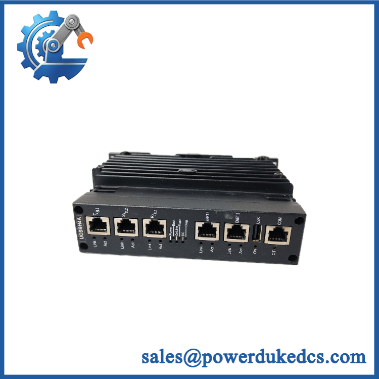
GE IS420UCSBS1A
Application Scenarios & Pain Points
When the controller fails, the problem is usually system-wide rather than confined to one field signal. The UCSBS1A is a processing and communications asset, so diagnosis has to begin at the controller, power, IONet, and application layers.
Gas Turbine Functional Safety
A Mark VIeS installation can use redundant UCSB controllers to execute safety-related turbine logic. During a controller fault, the maintenance team must determine whether the issue originates in the processor, network path, power supply, or loaded application before removing the hardware.
Burner Management Systems
In a burner-management application, controller execution and discrete/analog safety I/O must remain synchronized. GE’s Mark VIeS documentation shows UCSBS1A used in a documented burner-management-system bill of material.
Steam and Process Turbine Protection
For turbine protection functions, controller availability has a direct effect on system readiness. Keeping a verified UCSBS1A spare can reduce recovery time where a compatible safety-controller configuration cannot be sourced quickly.
Redundant Safety Architectures
The UCSB platform supports simplex, dual, and triple-controller arrangements depending on the system design. In a TMR installation, replacing one controller requires checking the remaining controller population and the IONet topology rather than treating the failed board as an isolated computer.
High-Temperature Control Cabinets
At 50°C+ cabinet ambient conditions, power consumption and thermal management deserve attention. The S1A/H1A generation uses convection cooling, so blocked airflow or elevated enclosure temperature can reduce operating margin even when the DC supply remains within tolerance.
🚨 Common Error Codes & Diagnostic Symptoms
Symptom/Code: BOOT/ON or controller status remains abnormal after power-up
→ Diagnosis: Possible boot failure, corrupted application image, flash-storage issue, processor fault, or unstable DC input.
→ Action: Verify the 28 VDC supply and controller diagnostics, preserve the existing application image, and replace the when the fault follows the controller.
Symptom/Code: Multiple I/O networks report communication loss simultaneously
→ Diagnosis: A common controller-side communication problem is more likely when several independent IONet paths become unavailable at the same time. Check controller power, IONet interfaces, and network switches before replacing multiple I/O modules.
→ Action: Isolate the controller from external network faults; replace the if the communication failure remains controller-local.
Symptom/Code: Controller repeatedly resets under normal load
→ Diagnosis: Potential causes include unstable power, processor hardware degradation, thermal stress, memory faults, or software-image corruption.
→ Action: Capture diagnostic records and temperature/power data first; replace the controller after external causes have been excluded.
🚨 Cross-Reference & Lifecycle Migration
Cross-Reference
- IS420UCSBS1A is the 600 MHz UCSB controller used in GE’s Mark VIeS safety platform.
- Related UCSB hardware includes IS420UCSBH1A, IS420UCSBH3A, and IS420UCSBH4A, but these should not be considered unrestricted substitutes.
- The processor frequency differs among these variants: H1A is 600 MHz, H3A is 1.2 GHz, and H4A is approximately 1.066 GHz.
- The S1A designation is significant because it identifies the safety-controller configuration used in the Mark VIeS architecture.
- should not be cross-referenced to a conventional distributed I/O pack merely because both use Mark VIe hardware conventions.
Firmware and Application Compatibility
Hardware replacement and application recovery are separate tasks.
Before commissioning a replacement controller:
- Record the original controller part number and revision.
- Capture the installed ControlST/ToolboxST version.
- Back up the safety application and configuration.
- Record controller IP parameters and IONet assignments.
- Confirm the approved QNX/software baseline.
- Validate the safety configuration before allowing the replacement controller into service.
The NVRAM/forced-variable behavior is also ControlST-version dependent on UCSB hardware. GE documentation identifies different nonvolatile-variable and totalizer capabilities between ControlST V07.04-and-earlier and V07.05-and-later environments, while noting that these NVRAM functions are not supported by Mark VIeS safety control. That makes software-baseline verification especially important.
Lifecycle Status
Status: Active platform component / availability subject to current procurement
GE’s published Mark VIeS documentation continues to identify as a Mark VIeS controller in the system bill of material. A current published GE North American certification record also includes among the covered controller models.
For inventory policy, classify it as a critical safety controller spare. One tested replacement should generally be reserved for each installation where controller failure can prevent the safety system from reaching its required operating state.
Field Engineer’s Tech Notes
Warning 1 — Do not copy the application from a conventional Mark VIe UCSB configuration into a Mark VIeS safety controller without checking the safety project baseline.
The hardware family is related, but the safety-system configuration is not simply a standard controller project with a different catalog number. Treat the safety application and its approved configuration as controlled engineering data.
Warning 2 — Do not diagnose an IONet failure by replacing the controller first.
Three IONet interfaces mean there are multiple network paths to investigate. Check each Ethernet cable, IONet switch, port status, controller power, and network topology before condemning the .
One useful warehouse practice: record the controller MAC/network identity and software baseline with the serial number. A physically good spare without configuration records can still produce a lengthy commissioning event.
Strict QA & Testing SOP
Step 1 — Inbound Identity Verification
Record:
- GE manufacturer marking
- catalog number
- UCSB designation
- Serial number
- Hardware revision
- Safety-system identification
- Manufacturing labels
Photograph the complete controller label before installation.
Step 2 — Physical Examination
Inspect:
- Housing
- Ethernet connectors
- USB/COM interfaces
- Mounting hardware
- PCB enclosure
- Connector contacts
- Signs of impact
- Moisture or corrosion
Pay particular attention to Ethernet jacks because IONet faults can be mistaken for controller failure.
Step 3 — DC Power Test
Use a regulated laboratory supply and apply the applicable 18–32 VDC operating range.
Record:
- Startup behavior
- Normal voltage
- Nominal operating current
- Peak current behavior
- Abnormal heating
Do not release a unit with unexplained current spikes.
Step 4 — Controller Boot Test
Verify:
- Power indication
- Boot sequence
- Processor initialization
- Memory detection
- Flash recognition
- QNX startup
- Controller diagnostic status
Step 5 — Ethernet and IONet Test
Exercise the relevant network interfaces and verify:
- ENET1 communication
- Applicable ENET2 behavior
- IONet Port 1
- IONet Port 2
- IONet Port 3
- Link stability
- Network packet exchange
- Diagnostic reporting
Step 6 — Application Test
Load an approved test image and verify:
- Control application execution
- Real-time logic processing
- I/O data exchange
- Controller diagnostics
- Network communication
- Controlled restart behavior
For a safety controller, the test application should remain isolated from the production safety system.
Step 7 — Extended Run
Run the controller under representative conditions and monitor:
- DC input stability
- CPU behavior
- Memory stability
- Ethernet communication
- IONet continuity
- Temperature
- Unexpected resets
Step 8 — Configuration Record
Document the tested:
- Hardware revision
- Software/QNX revision where accessible
- ControlST baseline
- Network parameters used in the test
- IONet test results
- Application-test results
Step 9 — Final QC
Release documentation should include:
- Exact catalog number
- Serial number
- Test date
- Technician
- Power measurements
- Boot results
- Memory/flash results
- Ethernet results
- IONet results
- Application test result
- Final QC disposition
Step 10 — Anti-Static Preservation
After testing, return the to an ESD-safe antistatic bag and protect the Ethernet/connectors against impact and contamination. Store it in a clean, dry environment away from condensation and excessive thermal cycling.
Test videos are available when visual evidence is included with the individual inspection package.
Buyer’s FAQ
A: Do not assume that controller removal is a routine hot-swap operation. The is part of a functional-safety control architecture, so replacement must follow the approved Mark VIeS maintenance and electrical-isolation procedure for the actual system configuration.
Q: Is the same as IS420UCSBH1A?
A: No. Both are 600 MHz UCSB-generation controllers, but S1A is identified for the Mark VIeS safety-controller architecture, while H1A is a different UCSB configuration. Do not substitute them without a GE-approved compatibility assessment.
Q: Does a New Original controller come with the plant’s safety application installed?
A: Do not assume it does. The physical controller, operating environment, firmware, safety application, network configuration, and project database are separate considerations. A replacement unit should be loaded and validated against the approved site configuration before service.
Q: What warranty should I require?
A: Specify warranty coverage against the serial number and supplied condition. For a critical Mark VIeS controller, acceptance should include documented power-up, CPU/memory initialization, Ethernet, IONet communication, diagnostics, and application-test results—not simply a statement that the controller powers on.











 Start Chat


