

Description
- Model: IS420YDIAS1B
- Brand: GE / GE Vernova
- Series: Mark VIeS
- Part Type: Discrete Input I/O Pack / Safety Contact Input Module
- Functional Acronym: YDIA
- Core Function: Provides the electronic interface between Mark VIeS safety discrete-contact inputs and one or two I/O Ethernet networks.
- Input Channels: 24 discrete inputs per I/O pack
- Input Type: Dry-contact / discrete contact input
- Typical Wetting Voltage: 24 VDC nominal with the corresponding 24 VDC TBCI configuration
- Ethernet: 2 × RJ-45
- Field Interface: DC-37 connection to the associated terminal board
- Power: 24/28 VDC
- Maximum I/O Pack Power: 6.8 W
- Architecture: Simplex, dual, or TMR system configurations
- Safety: IEC 61508 safety-rated when used in the defined Mark VIeS architecture
- Mounting: DIN-rail terminal-board system with direct I/O-pack mounting
- Operating Temperature: -40°C to +70°C
- Storage Temperature: -40°C to +85°C
- Diagnostic Functions: Power-up self-test, contact-input voltage loss detection, background input testing, and terminal-board identification checks.
Product Introduction
The GE IS420YDIAS1B is the discrete-input I/O pack used in the Mark VIeS Functional Safety System. It provides the electronics required to acquire 24 discrete contact inputs and exchange that information with the Mark VIeS control architecture through one or two I/O Ethernet networks. GE identifies the YDIA as a safety-rated module compliant with IEC 61508 when installed in the specified system configuration.
The YDIA is not normally installed as a standalone field termination device. It interfaces with a dedicated terminal board, with GE documenting compatible TBCI and STCI families for different input-voltage, redundancy, and terminal configurations. This distinction matters during replacement: the I/O pack and terminal board are separate orderable components, and substituting the wrong terminal-board version can produce an incorrect or rejected board configuration.
Core Technical Specifications
| Parameter | Specification |
|---|---|
| Manufacturer | GE / GE Vernova |
| Part Number | IS420YDIAS1B |
| Product Family | Mark VIeS |
| Functional Acronym | YDIA |
| Product Type | Discrete Input I/O Pack |
| Safety Function | Mark VIeS Functional Safety Contact Input |
| Input Channels | 24 discrete inputs per module |
| Input Type | Discrete contact / dry-contact input |
| I/O Pack Redundancy | Simplex, Dual, or TMR |
| Ethernet Interfaces | 2 × RJ-45 |
| Network Function | Interface between one or two I/O Ethernet networks and the discrete-input terminal board |
| Field Interface | 1 × DC-37 connector |
| DC Power Connector | Micro Mate-N-Lok receptacle, AMP 1445022-3 |
| Control Power | 24/28 VDC |
| Maximum I/O Pack Power | 6.8 W |
| Processor Architecture | Common processor board plus discrete-input acquisition board |
| Health Indication | Visual status LEDs and control-logic health variables |
| Diagnostic Functions | Power-up self-test; loss of contact-input voltage; background non-responsive-input test; incorrect-terminal-board detection |
| Sequence of Events | Yes |
| SOE Resolution | 1 ms sample rate |
| Contact Input Line Monitoring | No |
| Construction | Aluminum case |
| Mounting | DIN-rail-mounted Mark VIeS termination assembly |
| Operating Temperature | -40°C to +70°C |
| Storage Temperature | -40°C to +85°C |
| Safety Rating | IEC 61508 compliant in specified Mark VIeS configurations |
| Hazardous-Location Capability | Class I Division 2 / Class II Zone 2 / ATEX, subject to approved system configuration |
| G3 Compliance | Yes |
| Firmware / Application Logic | Module diagnostics and I/O processing; no standalone user application comparable to a UCS controller |
GE documentation specifies 24 inputs per YDIA, 24/28 VDC control power, and a maximum of 6.8 W per pack. It also identifies 1 ms SOE sampling and the principal diagnostic tests.
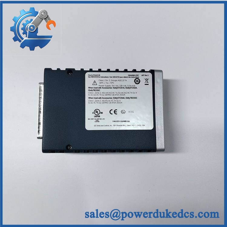
GE IS420YDIAS1B
Application Scenarios & Pain Points
Turbine Safety Contact Inputs
The YDIA is designed for discrete process signals such as permissive contacts, limit switches, pressure switches, valve-position contacts, and other binary status devices used within Mark VIeS safety logic. Each module handles 24 input channels, allowing a relatively dense group of contact signals to be acquired through one I/O pack.
Emergency and Protective Logic
Discrete safety inputs can participate in shutdown, permissive, trip, and interlock functions. A failed channel therefore deserves more scrutiny than an ordinary monitoring point: a misleading contact state can affect safety logic, while a failed acquisition path can create nuisance diagnostic conditions.
24 VDC Contact-Input Systems
For the 24 VDC TBCI architecture, GE specifies a nominal 24 VDC wetting supply at 110 mA, with a detection range of 20 to 32 VDC. The wetting source is floating to support ground-fault detection. That voltage specification belongs to the terminal-board/input configuration and should not be confused with the separate 24/28 VDC supply used to power the YDIA electronics.
TMR and Redundant Safety Architectures
The same IS420YDIAS1B I/O pack is used in simplex, dual, or TMR arrangements when paired with the appropriate Mark VIeS terminal-board architecture. GE documentation specifically lists the YDIA for TBCI configurations using one, two, or three I/O packs.
High-Temperature Control Cabinets
The specified ambient operating range extends to 70°C, but a cabinet consistently operating around 50°C or higher still deserves thermal inspection. High enclosure temperature, loose field terminals, degraded connectors, and unstable wetting power can all create symptoms that initially resemble an I/O-pack failure.
Common Error Codes & Diagnostic Symptoms
Symptom: Multiple discrete inputs show an abnormal state simultaneously
→ Diagnosis: Check the common terminal-board wetting supply, DC-37 connection, field wiring, and YDIA health indications. Multiple channels changing together are more consistent with a common interface or power problem than simultaneous contact-device failures.
→ Action: Replace module after verifying the terminal board and external wetting supply.
Symptom: A contact input remains unavailable despite a healthy field switch
→ Diagnosis: Verify the field contact, wiring continuity, terminal connection, input wetting voltage, and corresponding acquisition channel. GE specifically identifies loss of contact-input voltage and non-responsive contact-input detection as YDIA diagnostic functions.
→ Action: Replace module after isolating the fault to the I/O pack.
Symptom: Terminal-board configuration is rejected or diagnostic status indicates an incorrect board
→ Diagnosis: Check that the installed terminal board matches the YDIA-supported STCI/TBCI configuration and that the board is properly seated and identified. GE specifically documents incorrect-terminal-board detection.
→ Action: Replace module after confirming the terminal-board part number and connection.
No specific numerical GE fault-code list has been reliably verified for IS420YDIAS1B itself, so unsupported numeric codes should not be assigned.
Cross-Reference & Lifecycle Migration
The principal compatible terminal-board families include STCI and TBCI assemblies. GE documentation identifies the IS420YDIAS1B as the replacement I/O pack for several Mark VIeS discrete-contact-input configurations, including:
| Terminal Board | Input Configuration | YDIA Quantity |
|---|---|---|
| IS410TBCIS2C | 24 VDC contact input | 1, 2, or 3 |
| IS410TBCIS3C | 48 VDC contact input | 1, 2, or 3 |
| IS410STCIS2A | 24 VDC STCI configuration | 1, 2, or 3 |
| IS410STCIS4A | 48 VDC STCI configuration | 1, 2, or 3 |
GE’s documentation explicitly lists as the I/O-pack replacement part number for these defined Mark VIeS configurations.
Do not treat the voltage variants as interchangeable. A 24 VDC TBCI application and a 48 VDC TBCI application use different terminal-board assemblies even though both use the same YDIA I/O pack.
The public GE material reviewed identifies the YDIA as an active documented Mark VIeS component and continues to specify it in current Mark VIeS functional-safety documentation. A definitive manufacturer EOL date specifically for was not established from the available public documentation.
Spare-stock implication: For a safety-critical installation, maintain at least one tested spare and record the exact associated terminal-board model. A spare I/O pack without the correct terminal-board information is incomplete maintenance inventory.
Field Engineer’s Tech Notes
Tech Note 1 — Separate I/O-pack power from contact wetting power.
The YDIA electronics use 24/28 VDC control power with a maximum of 6.8 W, while the associated terminal board supplies the field-side contact wetting voltage. These are different power paths. Measure the correct circuit during troubleshooting; checking only the I/O-pack supply does not prove that the field contacts are being correctly energized.
Tech Note 2 — Verify the terminal-board voltage before installing the pack.
The same is used with both 24 VDC and 48 VDC contact-input terminal-board configurations. Do not infer the required field voltage from the YDIA part number alone. Check the installed TBCI/STCI part number and cabinet wiring diagram first.
Strict QA & Testing SOP
Step 1 — Inbound Inspection
Verify the complete marking, serial/revision information, GE identification label, aluminum housing, DC power connector, DC-37 connector, two RJ-45 ports, LEDs, and evidence of storage or transport damage.
Step 2 — Mechanical Inspection
Inspect connectors for bent or recessed contacts, examine the enclosure for deformation, and check the mounting interface. Verify that no unauthorized field modification or repair is present.
Step 3 — Power-Up Test
Apply a controlled 24/28 VDC supply within the specified operating configuration. Record startup behavior, current consumption, LED status, and internal diagnostic indications. GE specifies a maximum I/O-pack power of 6.8 W.
Step 4 — Ethernet Test
Verify both RJ-45 Ethernet interfaces using an appropriate Mark VIeS test environment. Confirm stable network link and communication behavior.
Step 5 — 24-Channel Input Simulation
Connect the I/O pack to the correct STCI/TBCI terminal-board configuration and exercise all 24 discrete inputs individually using controlled contact simulation. Record every channel response.
Step 6 — Diagnostic Verification
Test the expected diagnostic behavior, including power-up self-test and the relevant input/terminal-board detection functions. Where supported by the test setup, verify the 1 ms SOE acquisition behavior.
Step 7 — Redundancy-System Verification
For inventory intended for dual or TMR applications, verify that the tested pack is suitable for the exact terminal-board and redundancy architecture documented for the plant.
Step 8 — Extended Run Test
For critical spare inventory, operate the I/O pack for 24 hours or longer with representative input activity. Monitor supply voltage, communication status, channel stability, temperature, and unexpected diagnostics.
Step 9 — Final QC and Packaging
Record the part number, revision, serial number, terminal-board compatibility, electrical test results, all 24 channel results, and physical photographs. Package in ESD protection with connector protection and shock-resistant cushioning.
QC Documentation: Retain the test report and available functional test video with the spare inventory record so the safety I/O pack can be released quickly during an outage.
Buyer’s FAQ
Q1. What is GE ?
It is a Mark VIeS Discrete Input I/O Pack used for safety contact-input acquisition. Each pack provides 24 discrete input channels and interfaces with one or two I/O Ethernet networks.
Q2. Can one be used in a TMR system?
Yes. GE documentation specifies the for simplex, dual, and TMR configurations, with one, two, or three YDIA packs used according to the selected terminal-board architecture.
Q3. Is itself a complete field terminal assembly?
No. The YDIA is the I/O pack. The associated terminal board is a separate component. GE documents several compatible STCI/TBCI boards, including IS410TBCIS2C and IS410TBCIS3C.
Q4. What should be verified before purchasing?
Confirm the complete part number and revision, the associated terminal-board model, required 24 VDC or 48 VDC field-input architecture, redundancy arrangement, physical connector condition, and functional test evidence. For Mark VIeS safety applications, verify that the proposed replacement remains within the approved IEC 61508 and hazardous-location configuration.











 Start Chat


