

Description
- Brand: GE Multilin
- Full Model Number: PQMII-T20
- System/Series Family: Multilin PQM II
- Core Function: Three-phase electrical metering, power-quality monitoring, and programmable control
- Top 3 Hardcore Specs: 4-20 mA transducer outputs | 20-600 VAC voltage input range | 1 A / 5 A CT inputs
- Communications: RS232 + RS485; Modbus supported
- Display: 40-character illuminated display
- Data Logging: Up to 98,000 events
- Stock Status: New surplus, factory sealed, or fully tested refurbished subject to exact inventory confirmation
The GE Multilin PQM II is designed for continuous three-phase monitoring of current, voltage, real/reactive power, energy, power factor, frequency, and related electrical parameters. The T20 option specifically identifies four isolated analog outputs using the 4-20 mA range.
Module 3: Technical Product Introduction
A failed power-quality meter can leave an electrical distribution system without the measurements needed to diagnose load imbalance, abnormal voltage, demand excursions, or power-factor problems. The GE Multilin PQMII-T20 provides continuous three-phase measurement while the T20 transducer option supplies four isolated 4-20 mA analog outputs. The instrument also supports RS232 and RS485 communications, allowing measured values and status information to be integrated with supervisory systems.
The measurement architecture is specific enough to matter during replacement. GE documentation lists 1 A and 5 A CT secondary inputs, voltage measurement up to 600 VAC, and true-RMS conversion at 64 samples per cycle. The T20 outputs support a 4-20 mA range with a maximum load of 600 Ω and ±36 VDC isolation. The standard control-power range is 90-300 VDC or 70-265 VAC, although MOD 501 units use a different low-voltage supply range.
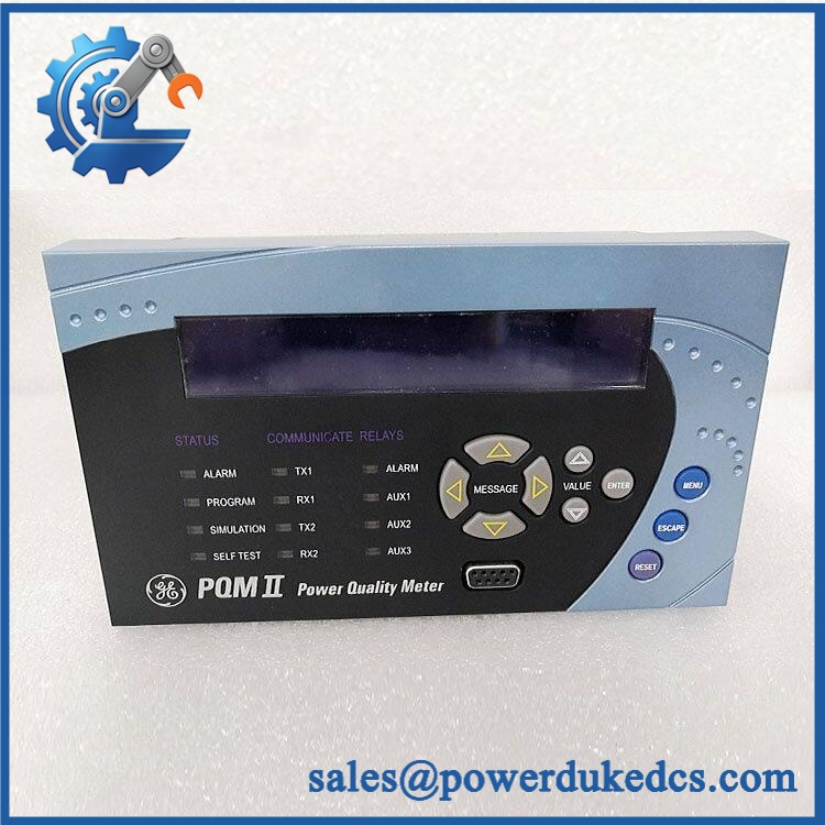
GE PQMII-T20
Module 4: Application Scenarios & Field Realities
- At distribution feeders and transformer incomers, the PQM II can monitor phase current, phase-to-phase or phase-to-neutral voltage, power, energy, frequency, and power factor. CT ratios and VT ratios must be entered correctly; a healthy meter with incorrect ratios can still produce misleading plant data.
- For PLC or DCS analog integration, the T20 option is particularly useful because its four isolated outputs can transmit selected measured parameters as 4-20 mA signals. Check the receiving input impedance before commissioning; GE specifies a maximum T20 output load of 600 Ω.
- On capacitor-bank installations, the meter can provide power-factor information and programmable control functions. GE specifically lists power-factor control and capacitor power-factor correction among PQM II applications.
- During electrical troubleshooting, the event recorder, waveform capture, harmonic analysis, and data logger provide more useful evidence than a single instantaneous meter reading. The PQM II can analyze harmonics through the 63rd harmonic and record up to 150 events, while the data logger capacity is listed at 98,000 events.
Module 5: Migration, Compatibility & Installation Traps
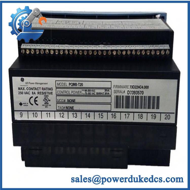
GE PQMII-T20
Replacement Matrix
| Replacement Type | Assessment | Engineering Requirement |
|---|---|---|
| Drop-in Replacement | Yes, when the complete PQM II configuration matches | Verify T20 option, control-power range, CT/VT inputs, communications, and terminal configuration |
| Software Compatible | Configuration-dependent | Restore setpoints, CT/VT ratios, analog-output assignments, communications, and alarm settings |
| Hardware Modification Required | Not normally required for an exact PQMII-T20 replacement | Confirm the original meter’s option code and modification numbers |
Field Traps — Watch Out
1. T20 is an option code, not merely a model suffix: GE’s order-code structure identifies T20 as the transducer option providing four isolated 4-20 mA analog outputs. A PQM II without T20 should not be assumed to have the same analog-output hardware.
2. Check the complete order code: GE documentation uses configurations such as PQMII-T20-C-A, where C adds three programmable output relays and four programmable switch inputs, while A adds power-analysis functions. The short designation “PQMII-T20” does not establish whether C or A is installed.
3. CT secondary rating: The PQM II accepts 1 A or 5 A CT secondaries. Verify the installed CT secondary before connecting the replacement meter. Never open-circuit an energized CT secondary during maintenance.
4. Firmware and processor revision: GE documentation notes that newer hardware revisions use a 25 MHz CPU, while older units may use 16 MHz. Certain functions, including the voltage disturbance recorder, require the newer processor platform. Record the existing firmware and hardware revision before replacement.
Module 6: Quality Assurance SOP
Before shipment, each GE Multilin PQMII-T20 should undergo a documented inspection sequence appropriate to the available meter test equipment.
- Step 1 — Part-number verification: Record , complete order code where available, serial number, modification number, firmware revision, processor revision, and manufacturing information.
- Step 2 — OEM anti-counterfeit visual inspection: Inspect GE/Multilin labels, front-panel display, keypad, terminal blocks, PCB markings, connectors, enclosure, and manufacturing identifiers. Photograph the model label and order-code information.
- Step 3 — Physical condition inspection: Check the enclosure, display, keypad, terminals, communication ports, and PCB for corrosion, contamination, cracked components, damaged connectors, loose hardware, or evidence of previous repair.
- Step 4 — Control-power verification: Confirm the unit’s actual control-power configuration before energization. Standard PQM II units use 90-300 VDC / 70-265 VAC, while MOD 501 units use 20-60 VDC / 20-48 VAC.
- Step 5 — Power-on self-test (POST): Energize the meter under controlled conditions and verify display initialization, keypad response, startup diagnostics, and available status indications.
- Step 6 — Measurement verification: Apply calibrated current and voltage signals appropriate to the configured CT and VT ranges. Verify representative phase-current, voltage, frequency, power, power-factor, and energy measurements.
- Step 7 — 4-20 mA output verification: For the T20 configuration, test all four analog outputs across representative points in the 4-20 mA range. Confirm output isolation and verify the receiving-load requirement where applicable.
- Step 8 — Communication handshake verification: Test the RS232 and applicable RS485 communication interfaces. Verify that the meter responds correctly to the intended protocol and that representative measured values can be read.
- Step 9 — Functional-option verification: Where the exact configuration includes C or A options, verify the applicable programmable relays, switch inputs, event recording, waveform capture, harmonic functions, or data logging.
- Step 10 — Final photographic record: Photograph the complete meter, model/order-code label, serial number, terminal area, display, communication ports, and final packaging.
QA release criterion: A successful power-up does not establish measurement accuracy. For a fully tested , the inspection record should distinguish between basic startup, calibrated measurement verification, 4-20 mA testing, communication testing, and option-specific functional testing.











 Start Chat


