

Description
- Brand: GE Multilin
- Full Model Number: SR465-P5-HI-A20
- Product Family: SR465 Multilin Feeder Management Relay
- Lifecycle Status: Legacy / Obsolescence-managed
- Core Function: Feeder protection, management, metering, and control
- Top 3 Technical Specs: 5 A phase CT inputs | HI control power | A20 analog-output configuration
- Control Power: 88–300 VDC / 70–265 VAC, 48–62 Hz
- Current Input: 5 A phase CT
- Analog Output: 8 × 4–20 mA
- Communications: RS-232 / RS-485 serial communications
- Display: Front-panel LCD with keypad
- Stock & Condition: New surplus / tested refurbished subject to physical stock verification
- Shipping: Emergency dispatch subject to stock confirmation and carrier cutoff
Obsolescence & Supply Chain Deep Dive
A failed SR465-P5-HI-A20 can become a procurement problem when a feeder protection scheme still depends on an installed GE Multilin SR-series relay. Available technical records identify the SR465-P5-HI-A20 as a Multilin feeder management relay, with P5 indicating 5 A phase-current inputs, HI indicating the high-range control-power configuration, and A20 identifying the analog-output configuration. The exact configuration should be verified from the relay nameplate before replacement because similarly formatted GE Multilin order codes can represent materially different protection hardware.
For lifecycle planning, retaining the existing relay architecture can avoid unnecessary panel rewiring, protection-setting redevelopment, SCADA mapping changes, commissioning, and outage work. The documented SR465 configuration includes programmable protection and control functions, event recording, metering, communications, and a front-panel programming interface. A verified replacement can therefore preserve an existing protection scheme when the surrounding switchgear remains serviceable (although an engineering review of the saved settings and firmware revision should precede energization).
Compatibility & Replacement Matrix
| Approval Item | Engineering / Procurement Guidance |
|---|---|
| Replacement Type | Drop-in replacement candidate for an identical SR465-P5-HI-A20 configuration |
| Software Compatibility | Existing protection settings should be backed up and compared; firmware revision must be verified before commissioning |
| Hardware Modification | Normally not expected for an exact relay replacement |
| Phase CT Inputs | 5 A |
| Control Power | 88–300 VDC / 70–265 VAC |
| Analog Outputs | 8 × 4–20 mA |
| Communications | Serial communications; interface configuration must match the existing scheme |
| Estimated Replacement Time | Approximately 2–6 hours for qualified protection personnel, excluding relay-setting validation |
| Engineering Cost | Primarily isolation, wiring verification, settings transfer, secondary injection, and commissioning |
| Migration Scope | Lower than a complete feeder-protection system replacement when the existing panel and wiring remain serviceable |
Field Traps — Watch Out
- CT secondary mismatch: P5 specifies 5 A phase CT inputs. Do not substitute a 1 A configuration simply because the enclosure and front panel appear similar. GE’s Multilin ordering documentation distinguishes 1 A and 5 A current-input variants.
- Control-power mismatch: HI is the high-range supply configuration. Available GE documentation identifies HI control power as 88–300 VDC or 70–265 VAC at 48–62 Hz. Verify the station control voltage before energization.
- Firmware and settings: The 469-series technical documentation demonstrates that GE Multilin relays retain specific order-code, firmware-revision, boot-revision, and calibration information. Treat the installed relay’s settings and revision data as part of the replacement approval record.
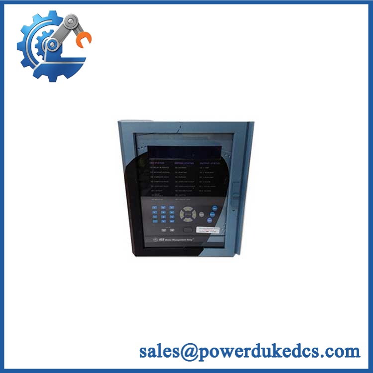
GE SR465-P5-HI-A20
Quality Assurance & Testing SOP
The is a protection and control relay, so QA should concentrate on identity, power-up behavior, metering, communications, protection logic, and output operation rather than generic PLC testing.
- OEM anti-counterfeit visual inspection: Verify GE/GE Multilin markings, model label, serial number, terminal identification, front-panel construction, keypad, LCD, and relay enclosure.
- Part-number reconciliation: Match the physical nameplate against -P5-HI-A20 and verify the complete ordering code.
- Configuration inspection: Confirm the P5, HI, and A20 configuration before functional testing.
- Mechanical inspection: Check drawout mechanism, terminal blocks, connectors, mounting hardware, front-panel controls, and enclosure for damage or deformation.
- Power-supply verification: Apply the appropriate AC or DC control power under controlled laboratory conditions and verify startup behavior.
- Display and LED test: Confirm LCD operation, status indicators, alarm indications, and keypad response.
- CT-input simulation: Apply controlled secondary-current signals to the 5 A phase-current inputs and verify measured values against the test source.
- Protection-function testing: Where the test set supports the applicable functions, inject representative current/voltage conditions and verify pickup, timing, alarm, and trip behavior against the approved settings.
- Analog-output load testing: Verify the 4–20 mA outputs using calibrated measurement equipment and representative output values.
- Communication test: Check the applicable RS-232/RS-485 interface, addressing, baud rate, and communication response using the intended protocol configuration.
- Event and diagnostic verification: Confirm event recording, fault indications, and accessible diagnostic information.
- Final QA record: Photograph the actual relay, record serial number and firmware information, document test results, and retain the inspection record with the shipment file.
Procurement & Lifecycle FAQ
Is the GE -P5-HI-A20 genuinely in stock, and what is the cutoff for emergency shipping?
Physical inventory should be confirmed before PO acceptance. For emergency requirements, provide quantity and destination early enough to complete part-number verification, functional inspection, packaging, and carrier scheduling.
How do you verify the condition and authenticity of a le?
The relay should undergo nameplate reconciliation, physical inspection, controlled power-up, display and LED checks, communications testing, and applicable protection-function testing. Actual-unit photographs can be supplied for engineering approval before shipment.
Are there firmware compatibility issues my engineers should check?
Yes. Record the existing relay’s firmware and boot revision before replacement and compare them with the replacement unit. Protection settings should also be backed up before removing the installed relay. GE Multilin documentation identifies firmware and boot-revision information as part of the relay’s product information.
replace another GE Multilin SR-series relay directly?
Not by series designation alone. Verify the complete order code, especially the P5 current-input configuration, HI control-power range, and A20 analog-output configuration. GE documentation shows that these order-code fields correspond to different hardware configurations.
What warranty and return terms apply?
Warranty duration and return conditions should be stated on the quotation or pro forma invoice for the actual unit supplied. For legacy or surplus protection relays, confirm the stated condition, test coverage, warranty period, and return requirements before PO issuance.











 Start Chat


