

Description
- Brand: GE Multilin
- Full Model Number: SR745-W2-P1-G1-HI-A-L-R
- System/Series Family: Multilin 745 Transformer Management Relay
- One-Sentence Core Function: High-speed transformer protection and management for two-winding transformer applications
- Top 3 Hardcore Specs: 2-winding configuration; 1 A phase CT inputs; 90–300 VDC or 70–265 VAC control power
- Stock Status: New Surplus / Fully Tested Refurbished subject to actual inventory inspection
Module 3: Commercial-Technical Deep Dive
Transformer protection failures are expensive because the relay sits directly between instrument transformers, trip logic, alarms, and the protected asset. The GE Multilin SR745-W2-P1-G1-HI-A-L-R is a configuration-specific 745 Transformer Management Relay for two-winding transformers. Its ordering code identifies W2 for two windings per phase, P1 for 1 A phase-current inputs on the windings, G1 for 1 A ground-current inputs, and HI for the high-range control-power option. The model also includes the A, L, and R options for analog inputs/outputs, loss-of-life functions, and restricted ground-fault protection.
The hard advantage is function density in a dedicated transformer relay. The 745 supports transformer protection, monitoring, metering, and management functions, with frequency tracking from 2 to 65 Hz around 50/60 Hz nominal operation. The HI control-power range accepts 90–300 VDC or 70–265 VAC at 48–62 Hz, while the protection platform includes restricted ground-fault elements and transformer thermal/loss-of-life calculations. Selected solid-state protection outputs can operate in tens of milliseconds under defined pickup conditions. In a replacement project, matching the complete ordering code is critical; a visually identical 745 with a different CT or power configuration can require wiring changes before it can be safely commissioned.
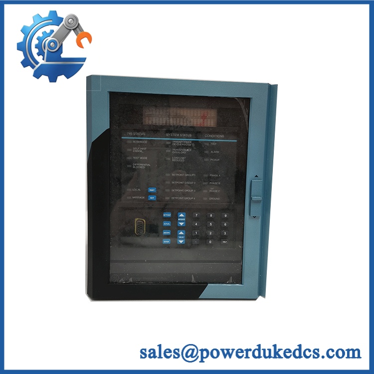
GE SR745-W2-P1-G1-HI-A-L-R
Module 4: Compatibility & Installation Traps
Migration/Compatibility
- Replacement status: Configuration-specific GE Multilin 745 Transformer Management Relay.
- Logic rewrite: Typically not required for a one-for-one replacement when the same hardware configuration and settings are retained.
- Firmware flash: Not automatically required. Verify firmware compatibility with the existing relay settings and application before altering the firmware.
- Configuration match: W2 / P1 / G1 / HI / A / L / R should be matched exactly when replacing this specific unit. The ordering-code structure defines winding count, CT ratings, power range, and protection/function options.
- CT input: P1 specifies 1 A phase-current input ratings for the applicable windings; G1 specifies 1 A ground-current inputs.
⚠️ Field Traps (Watch Out)
- CT mismatch: Do not substitute a 5 A phase-input version because the enclosure and front panel look identical. A P5 or mixed-current configuration has materially different CT input requirements.
- Control-power mismatch: The HI configuration accepts 90–300 VDC or 70–265 VAC. Applying a low-range control supply to a HI relay, or assuming the reverse, can stop commissioning or damage the power section.
- CT secondary safety: Never open an energized CT secondary. Before disconnecting the relay, follow the approved transformer-protection procedure for CT isolation and shorting.
- Protection-setting risk: A replacement relay can boot normally while its CT ratios, transformer configuration, trip logic, and restricted-ground-fault settings are wrong. Back up the original configuration before removal.
Module 5: Quality Assurance SOP
Before shipment, the GE SR745-W2-P1-G1-HI-A-L-R should undergo a protection-relay-specific QA sequence:
- OEM anti-counterfeit visual inspection — verify GE Multilin markings, complete ordering code, nameplate data, terminal arrangement, front-panel labeling, and enclosure construction.
- Mechanical inspection — examine terminals, draw-out mechanism, front display, keypad, mounting points, connectors, and visible PCB condition for damage or unauthorized modification.
- Configuration verification — confirm W2, P1, G1, HI, A, L, and R against the ordered unit and recorded nameplate.
- Power-input verification — confirm the test source is compatible with the HI control-power specification before energization.
- Power-on self-test (POST) — apply controlled power and verify startup behavior, display operation, status indications, and fault/self-diagnostic messages.
- CT/VT input simulation — use an approved relay test set to inject representative current and voltage signals and confirm measurement channels respond correctly.
- Protection-function verification — test selected transformer protection elements against documented pickup, timing, and configuration values.
- Restricted ground-fault verification — where the test setup supports it, validate the R-option protection scheme under controlled simulated conditions.
- Communication handshake verification — verify available engineering/service communications and confirm relay identification and data exchange.
- Output verification — test alarm/trip outputs using an isolated relay-test environment; do not connect an unverified output directly to a live transformer breaker.
- Final QC record — record catalog number, serial number where available, firmware revision, configuration, test results, photographs, and packaging condition.
A 745 relay should not be accepted simply because its display powers up. Current-input accuracy, configuration integrity, protection timing, and trip-output behavior are the meaningful acceptance points.
Module 6: CRO-Driven Buyer FAQ
1. Is GE SR745-W2-P1-G1-HI-A-L-R obsolete, and how do I verify an authentic replacement?
The 745 is a legacy transformer protection platform, so exact configuration and remaining inventory condition matter. GE’s documentation confirms the 745 ordering-code structure and the available W2, P1, G1, HI, A, L, and R options. Request a clear nameplate photograph and verify the complete SR745-W2-P1-G1-HI-A-L-R code rather than buying a generic “745.”
2. Can I hot-swap the SR745-W2-P1-G1-HI-A-L-R?
Do not treat this relay as hot-swappable. Transformer protection equipment interfaces with energized CT/VT circuits and breaker-trip circuits. Use a controlled maintenance shutdown, site LOTO procedure, and approved CT isolation/shorting procedure before removal.
3. Will an identical replacement require reprogramming?
Usually not a complete logic rewrite. A correctly matched replacement can use the existing protection settings, but CT ratios, transformer winding configuration, trip assignments, communications parameters, firmware compatibility, and option-dependent functions must be verified before energizing the protected circuit.
4. What does the HI-A-L-R configuration actually mean?
For this ordering code, HI identifies the high-range control-power option; A adds analog inputs/outputs; L enables loss-of-life functionality; and R provides restricted ground-fault functionality. W2 identifies a two-winding-per-phase transformer configuration, while P1 and G1 identify 1 A phase and ground current input ratings.
5. What warranty and technical support are available?
Warranty duration should be stated according to the actual inventory condition, such as new surplus or tested refurbished. Technical support should cover complete model verification, CT/control-power compatibility, configuration review, and documented bench-test results. Live transformer commissioning, protection coordination, and trip-circuit authorization remain the responsibility of the customer’s qualified protection team.











 Start Chat


