

Description
- Brand — GE Multilin
- Full Model Number — UR8CH
- System/Series Family — Multilin Universal Relay UR Series
- Core Function — CT/VT input module for acquiring power-system current signals for UR relay protection and measurement functions
- Top 3 Hardcore Specs — 3 × phase CT inputs rated 1 A/5 A; 1 × ground CT input rated 1 A/5 A; approx. 6 × 7 × 1.5 in module size
- Stock Status — New Original Stock; physical availability subject to final stock check
Technical Product Introduction
When a legacy Multilin relay loses a CT/VT input module, replacing the complete protection relay can create unnecessary configuration work and extend an outage. The GE Multilin UR8CH is an older CT/VT module used within the Universal Relay architecture, providing the relay with three phase CT inputs selectable for 1 A or 5 A secondary circuits and one 1 A/5 A ground CT input. Its role is concentrated on analog current acquisition rather than relay logic or communications. GE’s UR architecture separates CT/VT, CPU, power supply, digital I/O, and communications functions into modular hardware.
The physical module is listed at approximately 6 × 7 × 1.5 inches, with one technical reference reporting about 1.15 kg. More important during replacement is the firmware generation: published UR service information identifies UR8CH as an older CT/VT order code associated with the earlier hardware generation, while newer CT/VT modules and CPUs require a different firmware relationship. A same-part-number replacement is therefore a very different job from migrating an older UR installation to a newer CT/VT design.
Application Scenarios & Field Realities
- Generator protection panels often depend on stable phase-current and ground-current acquisition for functions such as overcurrent, differential, and other protection elements. Replacing the CT module while retaining the existing UR relay configuration can limit the scope of an outage — provided the replacement matches the installed hardware generation.
- Transformer protection cabinets are a common maintenance point because CT ratio, phase assignment, and grounding arrangements directly affect relay calculations. The UR8CH’s three 1 A/5 A phase CT inputs plus one 1 A/5 A ground CT input fit installations built around conventional secondary CT circuits.
- Legacy substation retrofit work requires more than checking the front label. Older CT/VT modules can be tied to older CPU and firmware combinations, so the maintenance engineer should identify the existing CPU module, relay model, hardware revision, and firmware before approving a spare. AX Control specifically identifies the UR8CH as an older CT/VT order code.
- During a forced replacement after a hardware fault, the practical priority is restoring the original measurement architecture without changing CT ratios or field wiring by accident. Keep the existing terminal schedule and relay setting file beside the work package; do not rely on memory or module appearance alone.
Migration, Compatibility & Installation Traps
Replacement Matrix
| Replacement Case | Classification | Engineering Requirement |
|---|---|---|
| UR8CH replacing the same in the existing UR relay | Drop-in Replacement | Verify part number, hardware revision, wiring, CT ratio, and installed CPU/firmware before energization |
| replaced by a newer CT/VT module within the UR family | Software Compatible | Confirm CPU compatibility and firmware generation; setting-file review may be required |
| migrated to a non-UR protection platform | Hardware Modification Required | Re-engineer CT interfaces, terminal wiring, scaling, settings, and protection logic |
The firmware issue deserves particular attention. A published UR technical reference states that older CPU/CT-VT combinations are associated with firmware 3.5x or earlier, while newer CT/VT modules and CPUs are associated with firmware 4.0x and newer. This should be treated as a compatibility checkpoint, not as permission to upgrade firmware automatically.
Field Traps — Watch Out
CT secondary open-circuit risk: Never disconnect or leave an energized CT secondary open. Before moving any CT wiring, follow the site’s approved CT shorting and isolation procedure. The danger is electrical, not software-related.
1 A versus 5 A mismatch: The accepts 1 A or 5 A CT secondary circuits, but that does not make the two ratings interchangeable in an installed protection scheme. Check the actual transformer ratio, relay settings, wiring designation, and commissioning records before transferring conductors.
Firmware generation: Do not assume a newer CPU or CT/VT module can be mixed with an older simply because the module fits the same UR chassis. Hardware generation and firmware must be evaluated as a system.
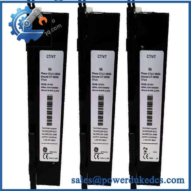
GE UR8CH
Quality Assurance SOP
Our pre-shipment inspection is structured around identification, electrical condition, and functional verification:
- OEM anti-counterfeit visual inspection — compare GE identification labels, part number, serial markings where present, housing details, connector construction, PCB condition, and evidence of unauthorized modification.
- Mechanical inspection — examine terminal interfaces, mounting hardware, connector pins, board seating surfaces, contamination, corrosion, and physical impact marks.
- Power-on self-test (POST) — place the module in the applicable UR test configuration and inspect the host relay’s diagnostic state, including ERR/RUN LEDs where provided by the installed hardware.
- CT input verification — apply controlled secondary test signals to the applicable phase and ground channels and confirm that the UR relay recognizes the expected current measurements.
- Ratio and channel verification — confirm the configured 1 A/5 A input arrangement against the test setup and verify phase/channel identification.
- Communication handshake verification — connect the relay engineering interface and confirm that the host UR device recognizes the installed hardware and returns expected diagnostic data.
- Configuration review — compare the tested module against the specified UR relay configuration and record hardware or firmware generation before shipment.
- Final QA record — photograph the unit, record the exact model number, document test observations, apply ESD protection, and package the module for shipment.
For surplus inventory, the critical distinction is between a module that merely powers up and one that has been checked against the expected UR measurement path. The latter requires controlled CT simulation, host-relay recognition, and configuration verification before release.











 Start Chat


