

Description
- Brand: GE Multilin / General Electric
- Full Model Number: UR8LH / UR-8LH
- System/Series Family: GE Multilin Universal Relay Series
- Core Function: CT/VT input module providing four current-transformer channels and four voltage-transformer channels with enhanced analog-signal diagnostics
- Top 3 Hardcore Specs: 3 × phase CT inputs at 1 A/5 A + 1 × ground CT at 1 A/5 A; 4 × VT inputs; 50/60 Hz system frequency
- Stock Status: New Surplus — availability and exact revision to be confirmed before order
Technical Product Introduction
A failed CT/VT input module can remove the relay’s access to the electrical quantities it needs for protection, metering, and event analysis. The GE Multilin UR8LH is a dedicated CT/VT module for the UR platform, providing the standard 4CT/4VT arrangement with enhanced diagnostics intended to verify analog signal integrity. Its channel arrangement comprises three phase CT inputs rated for 1 A or 5 A, one 1 A/5 A ground CT input, and four VT inputs; published specifications also identify 50/60 Hz operation.
For maintenance teams, the important distinction is not a claimed processing-speed figure but the module-generation relationship inside the UR architecture. Technical references identify the UR-8LH as a newer CT/VT module and report that newer CPUs and firmware from approximately 4.0x are required for the newer hardware, while older CPU/module combinations are associated with firmware 3.4x or earlier. That makes CPU revision checking part of the replacement decision rather than an afterthought (the exact relay model and installed configuration still need verification).
Application Scenarios & Field Realities
- In transformer protection panels, the four-CT/four-VT arrangement provides the analog current and voltage channels required by the host UR relay. During replacement work, confirm the existing CT secondary ratings and terminal assignment before reconnecting conductors; a wiring error can produce incorrect measured quantities even when the replacement module itself is healthy.
- For generator and feeder protection cabinets, the UR8LH is relevant where the installed relay already uses a 4CT/4VT configuration. The practical advantage is architectural: the module handles the CT/VT interface inside the UR platform rather than forcing a redesign of the relay enclosure. Exact protection functions remain dependent on the host relay model and its configured firmware.
- On utility or industrial substation panels, the enhanced diagnostic capability matters when troubleshooting intermittent analog-channel problems. A technician can separate a suspected CT/VT wiring issue from a module-level signal problem more methodically than with a basic like-for-like visual inspection alone.
- Where a legacy UR installation is being kept in service for lifecycle reasons, the UR8LH can serve as a replacement or upgrade module, but the CPU generation must be checked first. The recurring field trap is ordering the correct module number while overlooking the hardware-generation boundary inside the relay.
Migration, Compatibility & Installation Traps
Replacement Matrix
| Replacement Classification | Engineering Assessment |
|---|---|
| Drop-in Replacement | Conditional. A like-for-like UR8LH replacement is normally mechanically compatible within the intended UR modular architecture, subject to the exact relay model, CPU, and installed configuration. |
| Software Compatible | Yes, with qualification. Published technical references associate the newer UR8LH hardware with newer CPUs and firmware around 4.0x or later; older CPU/module generations are associated with 3.4x or earlier. Verify the installed CPU and firmware before energization. |
| Hardware Modification Required | Normally no for an approved like-for-like module replacement. Hardware modification may become necessary only when the target relay chassis, CPU generation, wiring configuration, or module type differs from the original installation. |
Field Traps — Watch Out
CPU and firmware mismatch: Do not assume that matching “” on the label makes the assembly interchangeable. Sources describing this module specifically warn that the newer CT/VT hardware should be paired with a compatible newer CPU, with firmware around 4.0x or newer reported for the newer combination. A mismatch can prevent normal relay operation.
CT secondary safety and polarity: Treat every CT circuit as energized unless proven otherwise. Never leave an energized CT secondary open-circuit during replacement work. Before installation, document CT polarity, phase assignment, ground CT wiring, and the 1 A versus 5 A secondary rating. This is a protection-engineering issue, not merely a terminal-label check.
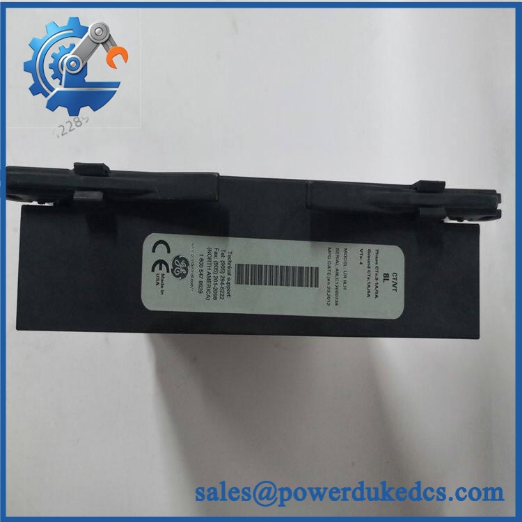
GE UR8LH
Quality Assurance SOP
Incoming identity inspection
- Verify GE / Multilin markings, model designation, nameplate information, and visible revision or date-code information.
- Inspect the enclosure, PCB area where accessible, rear connector, terminals, locking hardware, and mounting surfaces.
- Perform an OEM anti-counterfeit visual inspection against known GE Multilin construction details and supplied identification data.
Mechanical and connector inspection
- Check the backplane connector for bent, recessed, oxidized, or contaminated contacts.
- Confirm that the module seats correctly in a known-compatible UR chassis without abnormal insertion force.
- Inspect terminal hardware for cracks, looseness, deformation, or evidence of previous overheating.
Power-on verification
- Install the module in a known-good test environment with a compatible UR relay assembly.
- Execute the power-on self-test (POST) and check the host relay ERR/RUN or equivalent status indications for normal startup behavior.
- Record any hardware mismatch, module identification, diagnostic, or configuration alarms before continuing.
CT/VT channel verification
- Use controlled secondary test equipment to verify the configured CT and VT input paths.
- Check the three phase CT channels, ground CT channel, and four VT channels for correct recognition and expected measurement behavior.
- Confirm channel assignment, polarity, scaling, and phase relationship against the intended test configuration.
Communication handshake verification
- Verify that the host CPU recognizes the module through the internal relay architecture.
- Confirm normal module identification and absence of communication or hardware-mismatch diagnostics.
- Where EnerVista UR software is used in the installed system, verify that the relay configuration can read the expected module information.
Final shipment record
- Photograph the model label and physical condition.
- Record test status, observed revision information, and packaging condition.
- For surplus inventory, keep the inspection record with the serial or identification data used for shipment traceability.











 Start Chat


