

Description
- Brand: GE
- Full Model Number: VLC-853-E
- System / Series Family: GE Industrial Control / Variable Load Control
- Core Function: Variable-load control module for industrial power or motor-control equipment
- Top 3 Hardcore Specs: VLC controller architecture / E revision / Industrial control application
- Module Type: Variable Load Controller
- Model Family: VLC-853
- Revision: E
- Interface / Protocol: Application-dependent; verify from the installed system documentation
- Stock Status: New Surplus / Factory Sealed — exact physical condition to be confirmed before quotation
Module 3: Technical Product Introduction
A variable-load controller sits at the point where changing process demand has to be translated into controlled equipment response. The GE VLC-853-E is identified by its VLC-853 model designation and E revision as an industrial variable-load control component. Because publicly available technical references for this exact ordering code are limited, it is important not to assign unsupported voltage, current, I/O count, or communications specifications to the unit simply from the model number.
For replacement work, the exact equipment application is therefore the first engineering checkpoint. The VLC-853-E should be matched against the existing cabinet BOM, wiring diagram, nameplate information, connector arrangement, and controller configuration before procurement. —A physical photograph of the installed module is particularly useful when dealing with older GE equipment, where revision suffixes can determine whether a nominally similar assembly is actually suitable.
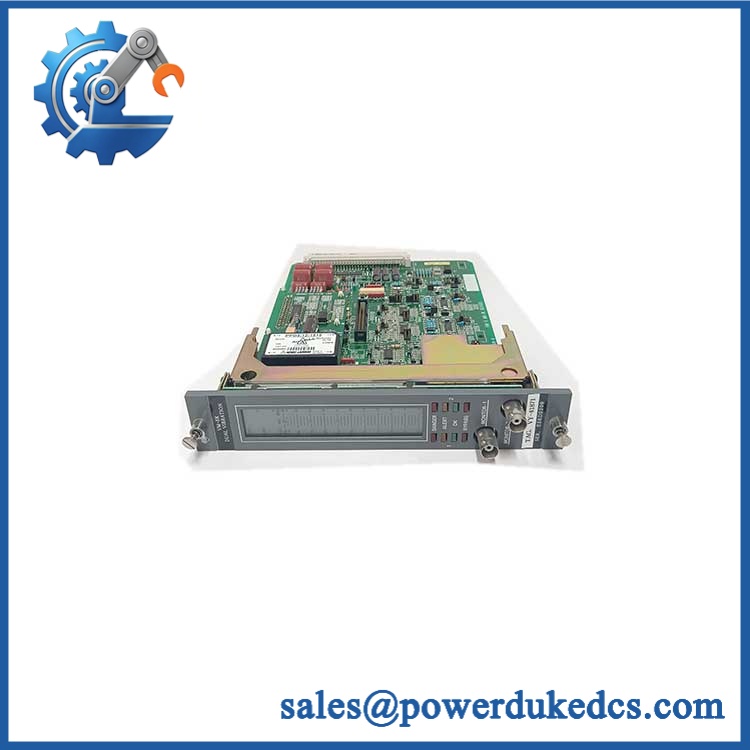
GE VLC-853-E
Module 4: Application Scenarios & Field Realities
- In industrial load-control assemblies, the VLC-853-E can be evaluated as part of the control path that responds to changing equipment demand. The correct replacement depends on the specific GE system in which the controller is installed.
- During a legacy equipment shutdown, technicians should record every connector and terminal assignment before removing the failed unit. Older control cabinets often contain field modifications that are not reflected in the original documentation.
- For variable-load machinery, check the relationship between the controller and the final controlled device. A controller replacement should be evaluated together with its power interface, feedback signals, and control logic rather than as an isolated circuit board.
- When maintaining obsolete GE hardware, the E suffix deserves attention. Do not substitute another revision merely because the enclosure and connector layout appear identical. Verify the complete ordering code and application first.
Module 5: Migration, Compatibility & Installation Traps
Replacement Matrix
| Replacement Case | Classification | Engineering Requirement |
|---|---|---|
| -E replacing the identical -E | Drop-in Replacement | Verify complete part number, cabinet position, connectors, wiring, and configuration |
| Another revision | Software Compatible — Verify First | Confirm hardware revision, firmware/configuration requirements, and system documentation |
| Different VLC controller family | Hardware Modification Required | Recheck I/O, power interfaces, feedback signals, mounting, and control logic |
| Different GE control architecture | Hardware Modification Required | Do not substitute based on physical appearance alone |
Field Traps — Watch Out
Incomplete public specifications: The is not sufficiently documented in the available references to safely state detailed electrical ratings, I/O counts, or communications protocols. Do not populate a procurement specification with guessed values.
Revision mismatch: Preserve the complete identifier. The E suffix should be treated as an important hardware-revision marker until the applicable GE documentation confirms interchangeability with another revision.
Wiring documentation: Before removal, photograph the complete installation and record terminal numbers. On older industrial equipment, field wiring can differ from the original factory configuration.
Do not infer protocol: There is insufficient evidence to identify Modbus RTU, Ethernet, Profibus, or another communications protocol specifically for this model. Verify the actual interface from the installed equipment documentation or the physical unit.
Module 6: Quality Assurance SOP
The pre-shipment inspection fo should follow a controlled component-verification procedure:
- Part-number verification — Confirm the physical identificat and record all visible GE markings, serial information, revision details, and traceability identifiers.
- OEM anti-counterfeit visual inspection — Examine labels, PCB markings, connector construction, enclosure details, component markings, and manufacturing identifiers for inconsistent printing or unauthorized alteration.
- Mechanical inspection — Check the housing, mounting points, connectors, terminal interfaces, PCB edges, and accessible components for cracks, corrosion, deformation, contamination, or impact damage.
- Power-on self-test (POST) — Where an approved test fixture and verified electrical specification are available, energize the unit under controlled conditions and inspect applicable power, status, alarm, and fault indications.
- I/O verification — Test applicable input and output channels against the documented specification for the configuration. Do not assume channel assignments from another VLC revision.
- Control-response verification — Where the appropriate GE test environment is available, apply controlled input conditions and verify the expected controller response without exceeding approved operating limits.
- Communication handshake verification — If the ins configuration uses a communications interface, verify the actual interface and protocol from the system documentation before performing the handshake test.
- Configuration cross-check — Compare the tested unit against the customer’s cabinet BOM, existing module label, wiring documentation, and system configuration.
- Final inspection and packaging — Photograph the exact identification label, record test results, protect connectors and exposed PCB surfaces, apply appropriate ESD precautions, and package the unit against mechanical shock and moisture.
The final QA record should connect the identification, revision information, physical inspection, functional screening, configuration verification, and packing record to the unit shipped. For this relatively obscure GE model, documented identification is more reliable than extrapolating specifications from similarly named controllers.











 Start Chat


