

Description
- Brand: GE / VMIC catalog identification
- Full Model Number: VME-PMC-CADDY
- System/Series Family: VMEbus Industrial Computing Platform
- Core Function: VME carrier board for installing up to two single-width PMC modules or one double-width PMC module
- Top 3 Hardcore Specs: VME64 interface; UNIVERSE II CA91C142 VME-PCI bridge; A32/D32 bus operation
- Stock Status: New Surplus — stock confirmation required
Technical Product Introduction
When a legacy VME computer needs another PMC function, replacing the entire VME controller is often unnecessary. VME-PMC-CADDY provides the carrier layer required to integrate PMC expansion hardware into a VMEbus chassis. The documented design accepts up to two single-width PMC modules or one double-width module, with the PMC I/O routed through the VMEbus P2 connector. The carrier uses a UNIVERSE II CA91C142 VME-to-PCI bridge and can operate as either a VMEbus master or slave.
From a hardware-integration standpoint, the board supports A32, A24, and A16 addressing and D8, D16, and D32 data transfers. The published hardware dimensions are 160 × 233 mm, with a 6U × 4TE VME form factor; the standard version is specified for 0 to 50°C ambient operation, while an extended-temperature option is available for -40 to +75°C. Weight is approximately 250 g according to the hardware manual.
Important identification note: The official manufacturer documentation currently identifies VME-PMC-CADDY as an esd electronics product, order number V.1911.01. Some industrial spare-parts catalogs associate this model with GE/VMIC equipment. Before procurement, compare the board label, revision, order number, and existing chassis documentation rather than relying on the brand field alone.
Application Scenarios & Field Realities
- Legacy VME controller expansion: Where an installed VME chassis still has serviceable CPU and backplane hardware, the carrier provides a route for adding PMC-based functionality without replacing the complete VME computer. Check available backplane resources first.
- PMC-based data acquisition: A single-width PMC module can be installed on the carrier and connected to the VME system through the carrier’s bridge architecture. This arrangement is useful for maintaining older instrumentation and industrial-computing platforms where the PMC card remains available but the original carrier has failed.
- Two-card VME installations: Two single-width PMC modules can be accommodated simultaneously. The electrical design routes their I/O through the VMEbus P2 interface, so the P2 pin assignment of the installed PMC cards must be checked before energizing the chassis.
- Legacy software environments: The manufacturer’s documentation lists OS-9 and VxWorks among the supported operating systems. In an existing installation, however, the actual driver, BSP, PCI enumeration, and PMC device support depend on the host CPU and software image. Do not treat operating-system support as proof of application-level compatibility.
Migration, Compatibility & Installation Traps
Replacement Matrix
| Replacement Type | Assessment | Engineering Requirement |
|---|---|---|
| Drop-in Replacement | Conditionally applicable | Confirm board revision, VME backplane, PMC format, P2 wiring, and chassis dimensions |
| Software Compatible | Configuration verification required | Confirm PCI enumeration, operating system support, BSP, and PMC driver availability |
| Hardware Modification Required | Not normally required for a matching carrier | Modification may be required if the existing PMC uses a non-standard P2 pin assignment |
Field Traps — Watch Out
PMC mechanical format: The standard carrier accepts two single-width PMC modules or one double-width module. Confirm the installed card’s physical dimensions and mounting-hole pattern before installation. A mechanically similar card is not necessarily electrically compatible.
P2 pin assignment: The carrier routes PMC I/O to VMEbus P2. This makes the PMC’s I/O pin definition a critical compatibility item. The manufacturer also documents a -32P2 option with an alternative P2 pin assignment. Do not install a standard and -32P2 configuration interchangeably without checking the wiring and PMC documentation.
PCI enumeration: The VME-PCI bridge provides the connection between the PMC side and VMEbus architecture, but successful hardware installation does not guarantee that the host software will recognize the PMC device. Check the system’s PCI configuration, BSP, driver, and device initialization sequence after replacement.
VME backplane installation: Power down and isolate the VME chassis before removing the carrier. Inspect both VME connectors for bent contacts or contamination. The board uses two 160-position VME connectors in accordance with the VME64 extension arrangement.
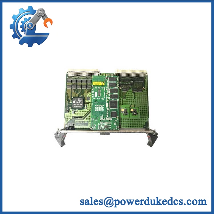
GE VME-PMC-CADDY
Quality Assurance SOP
Each available VME-PMC-CADDY should pass a documented inspection sequence before shipment:
- OEM anti-counterfeit visual inspection: Check manufacturer markings, model identification, PCB layout, connector arrangement, bridge-device markings, revision information, and board construction against documented hardware references.
- Part-number verification: Confirm the physical board marking corresponds to VME-PMC-CADDY and, where present, reconcile the order number with V.1911.01.
- Mechanical inspection: Examine the 160 × 233 mm PCB, front panel, mounting points, VME connectors, PMC mounting locations, and retaining hardware for impact damage or deformation.
- PMC slot inspection: Check both PMC positions for damaged connectors, foreign material, bent contacts, or signs of previous mechanical stress.
- VME interface inspection: Inspect P1/P2 connector condition and verify that the board has no visible contamination, cracked solder joints, or damaged components.
- Power-rail verification: On an appropriate laboratory fixture, verify the applicable carrier-board supply rails before installing a valuable PMC card.
- PCI bridge verification: Confirm recognition and expected operation of the UNIVERSE II bridge within a compatible VME test system where the required test platform is available.
- PMC enumeration check: Install a known-good compatible PMC module and verify that the host system can detect the device through the carrier.
- VMEbus access verification: Test representative VMEbus read/write operations using an approved diagnostic environment.
- Final inspection: Record model number, board revision, visible condition, test results, packaging condition, and inspection status before shipment.
Procurement note: VME-PMC-CADDY is a VME carrier board rather than a CPU, I/O controller, or standalone PMC module. The official product documentation identifies it as an esd electronics VME carrier, order number V.1911.01, with PCI and VME interfaces and support for OS-9 and VxWorks. If your installed spare-parts database identifies it as GE/VMIC, verify the physical board marking and revision before ordering.











 Start Chat


