

Description
- Brand — GE
- Full Model Number — VMER-64
- System/Series Family — GE VMEbus / VMIC Embedded Computing
- Core Function — Fiber-optic reflective-memory interface for deterministic data exchange between VME-based computing nodes
- Top 3 Hardcore Specs — VMEbus architecture; fiber-optic memory interface; reflective-memory data sharing
- Stock Status — New Surplus — exact board revision and serial-level availability to be confirmed
Publicly indexed technical records consistently associate the GE VMER-64 with a fiber-optic memory or reflective-memory function, although available listings disagree on several secondary specifications and even on the exact board family designation. The product identity should therefore be checked against the physical GE label and PCB revision before a purchase order is finalized.
Technical Product Introduction
A VME system can remain fully powered while its inter-node data path is effectively unavailable. That becomes a serious maintenance problem when several processor cards depend on shared memory information rather than point-to-point software transfers. The GE VMER-64 is publicly identified as a fiber-optic memory interface associated with GE’s VME/VMIC embedded-computing ecosystem. In a reflective-memory architecture, data written by one participating node can be propagated to other nodes through the optical network, reducing the need for repeated CPU-managed transfer operations.
For replacement work, the important specification is the interface architecture, not an unverified headline bandwidth figure. One current technical listing describes the VMER-64 as a reflective-memory module and publishes figures such as 128 MB/256 MB memory, 2.12 Gbaud serial signaling, and multi-node operation, but those values are not corroborated by an OEM document located in the public sources reviewed. They should therefore be treated as to be verified from the exact hardware revision. The safe engineering assumption is simpler: this is a legacy fiber-optic/VME memory-interface board whose original system configuration must be matched rather than replaced by a superficially similar VME card.
Application Scenarios & Field Realities
- In legacy VME test and simulation equipment, the VMER-64 is relevant where several processing nodes need a common high-speed data image. The optical link is particularly useful when deterministic data propagation matters more than conventional Ethernet-style messaging. A replacement should be tested with the actual node topology rather than only with a bench power supply.
- For distributed embedded control cabinets, reflective-memory hardware can provide a shared-data mechanism between processor nodes without requiring every data exchange to be handled by application software. Public descriptions of the VMER-64 specifically associate the board with real-time data sharing and multi-node interaction.
- During refurbishment of obsolete VME systems, the physical board revision deserves attention. One marketplace-independent technical listing identifies a separate memory-board configuration, while another identifies the same model as a different VME-related assembly. That conflict is precisely why receiving inspection should compare the complete PCB, connector arrangement, labels, and revision marking before installation.
- Where long copper data paths create grounding or EMI concerns, an optical interconnect can provide galvanic isolation between equipment sections. Do not assume the automatically supports every fiber type or optical connector found in the cabinet; those interface details must be established from the installed board.
Migration, Compatibility & Installation Traps
Replacement Matrix
| Replacement Case | Classification | Engineering Requirement |
|---|---|---|
| replacing the same hardware | Drop-in Replacement | Match PCB revision, connectors, VME slot requirements, optical interface, and host configuration |
| replaced by another GE reflective-memory board | Software Compatible | Verify memory mapping, device drivers, API behavior, firmware, and optical-network configuration |
| replaced by a different VME or Ethernet architecture | Hardware Modification Required | Re-engineer bus interface, addressing, data-sharing mechanism, cabling, and host software |
The most important trap is model-name ambiguity. Public product records describe as a high-speed fiber-optic memory module, while other listings assign the same designation to unrelated VME hardware. That means a purchase request containing only “” is not sufficient for a controlled maintenance replacement. Request a photo of the existing board label and PCB before approving a substitution.
Field Traps — Watch Out
Optical interface mismatch: Confirm the connector style, transmit/receive orientation, fiber type, wavelength, and optical budget before reconnecting the link. A physically compatible connector does not prove optical compatibility.
VME slot and system configuration: Power down the chassis unless the specific VME platform explicitly supports live insertion. Check slot position, backplane keying, address allocation, interrupt configuration, and any board-specific jumpers or switches before startup.
Memory-map mismatch: Reflective-memory hardware depends on the host system recognizing the board at the expected address and interface configuration. A card that powers up without errors is not necessarily communicating correctly with the application.
Revision control: Record the installed PCB revision and all visible assembly numbers before removing the failed board. This is especially important for because publicly indexed product information is not consistent enough to establish one universal hardware configuration.
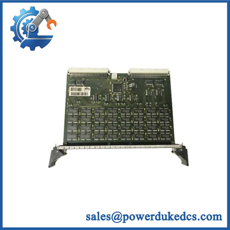
GE VMER-64
Quality Assurance SOP
The pre-shipment inspection should be handled as a board-level VME and optical-interface verification procedure:
- OEM anti-counterfeit visual inspection — compare GE labeling, part number, assembly identifiers, PCB layout, connector construction, component population, revision markings, and evidence of unauthorized rework.
- Mechanical inspection — inspect the VME card edge, optical connectors, mounting hardware, board surface, guide hardware, and exposed contacts for corrosion, contamination, cracks, bent pins, or impact damage.
- Power-on self-test (POST) — install the board in an appropriate VME test chassis and verify the expected startup behavior. Check ERR/RUN or board-status LEDs where provided by the installed hardware or host system.
- VME bus recognition test — confirm that the host processor detects the board and that the expected address space can be accessed without bus faults.
- Memory-path verification — perform controlled read/write testing through the supported interface and confirm that returned data matches the transmitted test pattern.
- Optical-link verification — connect the applicable fiber path and check transmit/receive activity, link state, and error indications supported by the hardware.
- Communication handshake verification — establish a controlled node-to-node exchange and verify that data written by one participating node is correctly observed by the receiving node.
- Multi-node validation — where the test bench permits, introduce a second compatible node and verify shared-memory propagation rather than stopping at a single-board power test.
- Configuration check — record the tested board revision, host platform, optical interface used, and any firmware or driver dependencies identified during testing.
- Final QA record — photograph the actual unit, document serial and revision information, apply ESD protection, protect optical ports from contamination, and package the board for shipment.
For this legacy GE board, identity verification is part of functional QA. The available public records do not establish a single authoritative specification set for every listing, so the actual PCB designation, revision, connector arrangement, and system-level test result should take precedence over generic catalog descriptions.











 Start Chat


