

Description
- Brand: GE
- Full Model Number: VMIPMC-5565
- System/Series Family: GE VMEbus / VMIPMC PMC Carrier
- Core Function: VMEbus carrier board providing a PMC interface for compatible VME embedded computing systems
- Top 3 Hardcore Specs: VMEbus architecture | PMC interface | VME single-board carrier
- Board Type: VME PMC carrier
- Expansion Architecture: PMC
- Host Interface: VMEbus
- Application: Industrial embedded computing and VME-based control systems
- Stock Status: New Surplus — exact revision and packaging condition to be verified before shipment
Technical Product Introduction
A PMC-based expansion board is useful only when the carrier, host processor, backplane, and installed PMC device agree on the same electrical and mechanical architecture. The GE VMIPMC-5565 is a VMEbus PMC carrier board intended to integrate PMC functionality into a compatible VME system. In a typical installation, the carrier occupies a VME slot while providing the required interface between the host VMEbus environment and an attached PMC module.
The critical replacement parameters are the VMEbus interface, PMC form factor, connector arrangement, board revision, and host-system support. The VMIPMC-5565 should not be treated as a generic VME I/O card; its purpose is tied to the PMC expansion architecture. Publicly indexed documentation for this exact model does not provide sufficiently consistent evidence for a definitive processor, memory, power-consumption, or operating-system specification. Those values should be confirmed from the actual board revision and system documentation before procurement (particularly in older VME racks with application-specific backplane assignments).
Application Scenarios & Field Realities
- Within legacy VME embedded computers, the VMIPMC-5565 can provide the physical carrier interface required to integrate a PMC-based function into the existing VME architecture. The host board and PMC device must both support the intended interface.
- For systems using specialized PMC peripherals, retaining the original carrier can avoid rewiring or redesigning the VME backplane. Confirm the PMC module’s electrical interface and connector configuration before transferring it to another carrier.
- During maintenance of older VME control racks, a spare carrier can be valuable when the original board develops connector, PCB, or interface faults. Record the installed PMC module and host-board configuration before removing the carrier.
- When upgrading a VME system, the carrier should be evaluated as part of the complete architecture rather than as an isolated board. A modern replacement may require changes to the PMC device, driver software, VME addressing, and application configuration.
Migration, Compatibility & Installation Traps
Replacement Matrix
| Replacement Condition | Assessment | Engineering Requirement |
|---|---|---|
| Same VMIPMC-5565 revision and matching PMC configuration | Drop-in Replacement Candidate | Verify VME slot, PMC interface, connector arrangement, and host compatibility |
| Same model with different hardware revision | Software Compatible — verification required | Confirm host-board recognition and installed PMC support |
| Different VME PMC carrier | Compatibility Review Required | Compare PMC electrical interface, VME addressing, connector pinout, and mechanical dimensions |
| Non-PMC VME I/O board | Hardware Modification Required | Requires changes to the expansion architecture and potentially application software |
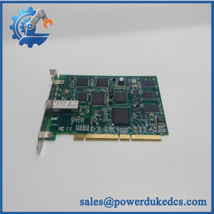
GE VMIPMC-5565
Field Traps — Watch Out
The PMC module itself must be identified. A carrier board does not determine the functionality of the complete system. Before replacement, record the exact PMC card installed on the VMIPMC-5565, including its manufacturer, model, revision, and connector configuration.
VME slot assignment can matter. Existing systems may use specific slot positions for system-controller, interrupt, address, or application functions. Reinstall the replacement in the original slot unless the system documentation specifies otherwise.
Connector damage is easy to overlook. Inspect both the VME connector and PMC interface before installation. Bent or recessed contacts can create intermittent faults that resemble software or backplane problems.
Do not hot-plug the board unless the complete VME system explicitly supports it. Power down and follow the equipment manufacturer’s maintenance procedure before removing or inserting the carrier.
Quality Assurance SOP
Before shipment, each available unit should pass a documented inspection sequence:
- OEM anti-counterfeit visual inspection — Verify GE identification, marking, PCB identifiers, revision markings, labels, and visible manufacturing references.
- PMC interface inspection — Examine the PMC mounting area, connector interfaces, mounting holes, standoffs, and retention hardware for physical damage or contamination.
- VME connector inspection — Check all VME connector contacts for bending, oxidation, contamination, recessed pins, or mechanical damage.
- PCB inspection — Inspect the board for corrosion, cracked components, damaged solder joints, overheating marks, missing components, and evidence of unauthorized modification.
- Mechanical verification — Check the board dimensions, ejector handles, faceplate, mounting hardware, and alignment features against the expected VME configuration.
- Controlled power-up test — Install the carrier in a compatible VME test chassis and verify normal power behavior and diagnostic status.
- VMEbus recognition verification — Confirm that the host test environment recognizes the carrier and that no abnormal bus fault occurs during controlled operation.
- PMC interface verification — Where a compatible PMC test module is available, install it and verify appropriate interface recognition and communication.
- Address and interrupt verification — Test the relevant VME resources where supported by the test environment and record any configuration requirements.
- Extended operation test — Run the board under controlled conditions long enough to identify abnormal heating, intermittent resets, bus errors, or unstable operation.
- Final identification check — Match the actual board model, hardware revision, installed options, and physical condition against the purchase order.
- ESD-safe packaging inspection — Package the carrier in suitable ESD protection with mechanical support around the VME and PMC connectors.











 Start Chat


