

Description
- Brand: GE
- Full Model Number: VMIVME-2128
- System/Series Family: GE VME / VMIC Industrial I/O
- Core Function: VMEbus digital I/O module for interfacing discrete field signals with a VME-based control system
- Top 3 Hardcore Specs: 32 digital I/O points | VMEbus interface | Front-panel field connections
- I/O Type: Digital input/output
- Channel Count: 32 points
- Bus Architecture: VMEbus
- Board Format: VME single-board module
- Stock Status: New Surplus — exact revision and packaging condition to be verified before shipment
Technical Product Introduction
A failed discrete I/O board can remove dozens of field signals from a VME control system at once. The GE VMIVME-2128 is a VMEbus digital I/O module from the VMIC family, providing 32 discrete I/O points for communication between field devices and a VME-based industrial computer or controller. In a typical installation, the board sits in the VME backplane while field wiring is brought to the module’s front-panel interface.
The 32-point architecture is the important maintenance characteristic. Instead of replacing a single field interface or rebuilding cabinet wiring, an exact VMIVME-2128 spare can preserve the existing VME slot architecture and signal mapping. Public references for this legacy module are not consistent enough to state a universal input-voltage range, output-current rating, or exact electrical mode for every hardware revision. Those values should be verified against the board documentation and installed revision before energization (particularly where external 24 VDC field circuits are involved).
Application Scenarios & Field Realities
- In legacy machine-control racks, the VMIVME-2128 can handle groups of discrete signals such as limit switches, permissive contacts, status indications, and actuator commands. Record the original channel map before replacing the board.
- Where a VME computer controls distributed equipment, 32 discrete points can consolidate multiple field signals on one VME module. The actual direction and electrical behavior of each channel must be confirmed from the installed configuration.
- During planned shutdown maintenance, technicians should photograph the front-panel wiring and label each field connection before removing the module. A connector that looks mechanically identical can still carry a different channel assignment on another revision.
- For legacy VME system preservation, maintaining an exact spare avoids forcing a migration to a different bus architecture. This can be important when the application software, driver layer, and I/O mapping were developed around the original VME hardware.
Migration, Compatibility & Installation Traps
Replacement Matrix
| Replacement Condition | Assessment | Engineering Requirement |
|---|---|---|
| Same VMIVME-2128 revision and matching I/O configuration | Drop-in Replacement Candidate | Verify slot, connector arrangement, channel mapping, and electrical ratings |
| Same model with different hardware revision | Software Compatible — verification required | Confirm host-driver support and I/O configuration |
| Different VME digital I/O board | Compatibility Review Required | Compare channel count, electrical characteristics, pinout, VME addressing, and software support |
| Different bus architecture | Hardware Modification Required | Requires changes to controller, backplane, wiring, drivers, and application configuration |
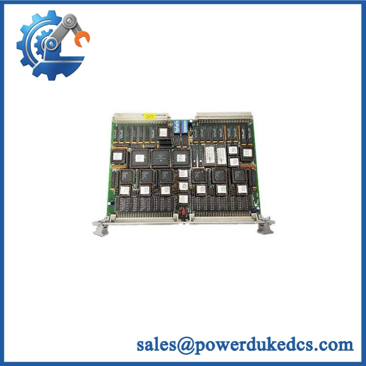
GE VMIVME-2128
Field Traps — Watch Out
Do not assume all 32 channels have identical electrical behavior. Before wiring the replacement, confirm whether the installed configuration uses inputs, outputs, or a specific mixed arrangement. Channel direction and electrical specifications must come from the applicable hardware documentation.
Front-panel pinout must be checked before reconnecting field wiring. A physically compatible connector does not guarantee identical signal assignment. Preserve the original wiring map and compare it against the replacement board.
Field voltage must be controlled. If the cabinet uses external 24 VDC or another field supply, verify the actual board input/output ratings before applying power. Never use an unverified voltage merely because another VME module in the rack uses it.
Avoid hot insertion unless the complete system is specifically designed for it. Shut down and isolate the VME rack according to the applicable maintenance procedure before removing the board.
Quality Assurance SOP
Before shipment, each available GE VMIVME-2128 unit should pass a documented inspection sequence:
- OEM anti-counterfeit visual inspection — Verify GE/VMIC markings, identification, labels, PCB identifiers, hardware revision, and manufacturing references.
- Front-panel inspection — Check the field connector, labeling, mounting hardware, ejector handles, and panel surface for damage or alteration.
- VME connector inspection — Examine all backplane connector contacts for bent, recessed, oxidized, contaminated, or damaged pins.
- PCB inspection — Inspect the board for corrosion, contamination, cracked components, damaged solder joints, overheating marks, and unauthorized modifications.
- Channel configuration verification — Confirm the expected 32-point digital I/O architecture and document the actual hardware revision.
- Controlled power-up test — Install the board in a compatible VME test chassis and verify normal power behavior and diagnostic status.
- VMEbus recognition verification — Confirm that the host VME system recognizes the board without abnormal bus errors.
- Digital I/O functional test — Where the test environment supports the installed configuration, exercise each applicable channel independently using controlled signal sources and loads.
- Channel mapping verification — Record the channel-by-channel response and compare it with the expected I/O assignment.
- Extended operation test — Monitor the board during controlled operation for intermittent resets, bus errors, abnormal heating, or unstable I/O behavior.
- Final identification check — Match the actual model, revision, configuration, and physical condition against the purchase order.
- ESD-safe packaging — Package the board in suitable ESD protection with mechanical support around the VME connector and field interface.
- Shipment release — Any discrepancy involving the model, revision, connector condition, or functional test result stops shipment until resolved.











 Start Chat


