

Description
- Brand: GE Fanuc / VMIC
- Full Model Number: VMIVME-4140-000
- System/Series Family: VMIVME VMEbus I/O Series
- Core Function: High-density digital input/output interface for VMEbus industrial and embedded computing systems
- Top 3 Hardcore Specs: 64 digital I/O points; VMEbus interface; programmable input/output direction by channel group
- Stock Status: New Surplus — stock confirmation required
Technical Product Introduction
A failed digital I/O board in a legacy VME control system can remove dozens of field signals at once. The GE Fanuc / VMIC VMIVME-4140-000 is a VMEbus digital I/O board intended to provide high-density discrete signal interfacing between a VME computer and external equipment. Its 64-channel architecture is suited to systems that need many individual status, alarm, interlock, or control points without consuming multiple VME slots. The board belongs to the VMIVME family of industrial VME hardware and should be evaluated together with the installed VME CPU, carrier, backplane, I/O wiring, and software driver.
For maintenance teams, channel density is the practical advantage. A single 64-point board can consolidate a substantial number of discrete signals while preserving additional VME slots for processing, communications, or other acquisition hardware. The actual electrical behavior depends on the specific I/O configuration, field wiring, jumper or configuration settings, and host software. For a replacement project, verify the original board revision, I/O voltage requirements, connector pinout, interrupt configuration, and driver support before applying field power — especially on older VMIC installations where documentation may differ by hardware revision.
Application Scenarios & Field Realities
- Legacy machine-control cabinets: Where a VME controller monitors numerous limit switches, proximity sensors, contactors, alarms, and permissive signals, a 64-point digital I/O board can concentrate those discrete channels in one VME slot. The field wiring should be documented before removing the existing board.
- Industrial test systems: Automated test equipment often requires many binary signals for fixture status, device-under-test conditions, safety interlocks, and sequence control. A high-density VME I/O interface can reduce the number of expansion boards required by the original architecture.
- Process equipment monitoring: In older process-control computers, digital points may include pump running status, valve position, motor trips, level-switch states, and external permissives. The board provides the VME-side interface, while the application software determines how those signals are interpreted.
- VME system refurbishment: During a planned maintenance outage, replacing a failed I/O board can preserve the existing CPU and application architecture. Before installation, compare the board’s connector pinout and electrical interface with the original hardware; identical model numbers from different revisions should still be inspected carefully.
Migration, Compatibility & Installation Traps
Replacement Matrix
| Replacement Type | Assessment | Engineering Requirement |
|---|---|---|
| Drop-in Replacement | Conditionally applicable | Confirm exact VMIVME-4140-000 revision, VME slot, I/O configuration, connector pinout, and field voltage |
| Software Compatible | Configuration verification required | Confirm driver, I/O address mapping, interrupt settings, and application configuration |
| Hardware Modification Required | Normally not required for an exact hardware match | May be required if field wiring, termination, or I/O electrical characteristics differ |
Field Traps — Watch Out
Electrical interface mismatch: Do not assume that every 64-channel VME digital I/O board uses the same field voltage or signal convention. Verify the original system schematic and board documentation before connecting external power.
Connector pinout: A replacement board can seat correctly in the VME backplane while the external I/O connector remains incorrectly wired. Photograph and label every field cable before removal, then perform a point-to-point check after installation.
VME address allocation: The host system must recognize the replacement board at the expected address range. Check the board configuration, jumper settings, or software-defined address assignment against the existing VME system.
Interrupt configuration: If the application relies on digital-input interrupts rather than polling, verify interrupt level and vector configuration after replacement. A board can pass a basic I/O test while interrupt-driven application functions remain inactive.
Field voltage application: Never connect an unverified external voltage source during initial testing. Start with the board isolated from plant wiring, establish the VME-side hardware status, then validate individual field channels under the site’s approved commissioning procedure.
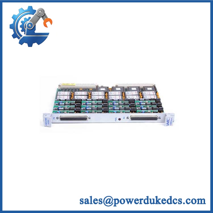
GE VMIVME-4140-000
Quality Assurance SOP
Each available VMIVME-4140-000 should pass a documented inspection sequence before shipment:
- OEM anti-counterfeit visual inspection: Inspect GE Fanuc / VMIC markings, model designation, PCB layout, component population, connectors, revision markings, and manufacturing identifiers.
- Part-number verification: Confirm the physical marking corresponds to VMIVME-4140-000 before release.
- Mechanical inspection: Check the VME card edge, backplane connectors, front panel, mounting hardware, external I/O connector, PCB surface, and solder joints.
- Connector inspection: Examine all VME and field-I/O interfaces for bent contacts, contamination, oxidation, cracked housings, or mechanical damage.
- Power-rail verification: On an appropriate laboratory fixture, verify the applicable VME supply rails before connecting external field wiring.
- Power-on self-test (POST): Install the board in a compatible VME test chassis and record startup behavior and available status indications.
- VMEbus recognition check: Confirm that the host VME controller detects the board at the expected address and that no bus errors occur during initialization.
- Digital I/O verification: Exercise representative input and output channels using controlled test signals and confirm the expected state transitions.
- Channel isolation check: Where supported by the test equipment, verify that activity on one channel does not produce an unintended state change on adjacent channels.
- Interrupt verification: If the installed configuration uses interrupts, generate representative input transitions and confirm correct interrupt response at the host controller.
- Final inspection: Record model number, board revision, visible condition, test results, packaging condition, and inspection status before shipment.
Procurement note: VMIVME-4140-000 should be matched against the complete legacy VME system configuration. Before ordering, verify the board revision, external connector pinout, electrical I/O characteristics, VME address configuration, interrupt requirements, and software driver. For older VMIC systems, these details can determine whether a physically identical replacement can be returned to service without changes.











 Start Chat


