

Description
- Brand: GE General Electric
- Full Model Number: WESDAC D20ME II
- System/Series Family: GE D20 / D200 RTU
- Core Function: Main processor and data-concentrator module for D20/D200 remote terminal systems
- Top 3 Hardcore Specs: 2 MB Flash; 512 KB NVRAM; 1.5 MB SRAM
- Communications: 7 configurable serial ports supporting RS-232 or RS-485; 1 RS-232 WESMAINT maintenance port
- System Variants: 526-2006 non-VME; 526-2007 VME
- Stock Status: New Surplus — exact board variant and condition to be verified before shipment
GE identifies the D20ME II as the D20/D200 main processor, with 526-2006 serving non-VME single-processor applications and 526-2007 serving VME D20/D200 systems. GE’s later supply notice lists 2 MB Flash, 512 KB NVRAM, and 1.5 MB SRAM for these D20ME II versions.
Technical Product Introduction
A D20 RTU outage becomes considerably harder to resolve when the main processor is unavailable, because the D20ME II is responsible for concentrating field data and controlling the D20 peripheral I/O modules. GE describes the D20ME II as functionally equivalent to the D20ME while adding per-channel selection between RS-232 and RS-485. The processor is available in both non-VME and VME configurations, so the installed chassis architecture has to be established before ordering.
The memory architecture is substantial for this legacy RTU platform: 2 MB Flash, 512 KB NVRAM, and 1.5 MB SRAM are documented for the later II versions. Communications are equally important during replacement work. Seven serial ports can be configured for RS-232 or RS-485, while the eighth serial connection is the RS-232 WESMAINT maintenance port. Each RS-485 port can support up to 32 devices and distances up to 4,000 feet without repeaters under the stated conditions.
Application Scenarios & Field Realities
- At electrical substations using D20 single-processor cabinets, the 526-2006 non-VME version is intended for this architecture. Before removing a failed processor, record the existing configuration and serial-port assignments; the replacement board still needs the correct D20 Base or CCU Base software environment.
- In a D200 multi-node installation, the VME version 526-2007 is the relevant hardware family. Its VME configuration determines the board’s role and address within the chassis, so swapping a non-VME board into this architecture is not a field shortcut. GE specifies that VME II modules can operate in multi-node D200 systems.
- Where RTU serial links run several hundred or several thousand feet, RS-485 is often the practical interface. GE specifies up to 32 devices per RS-485 port and up to 4,000 feet without repeaters; actual performance still depends on cable selection, grounding, topology, and transient exposure.
- During modernization of older D20M hardware, the replacement process is not simply “remove the old CPU and insert the new one.” GE documents a code-file conversion step for D20M-to- II upgrades, followed by Device Properties changes in Config Pro.
Migration, Compatibility & Installation Traps
Replacement Matrix
| Replacement Type | Assessment |
|---|---|
| Drop-in Replacement | Only for an identical II hardware variant with matching chassis architecture and configuration |
| Software Compatible | Yes within supported D20 Base or CCU Base environments; configuration verification required |
| Hardware Modification Required | Not normally required for an exact 526-2006-to-526-2006 or 526-2007-to-526-2007 replacement |
Field Traps — Watch Out
VME versus non-VME: GE separates 526-2006 non-VME and 526-2007 VME versions. The VME board also uses jumpers for master/slave operation and VME addressing. In a chassis, JP1 and JP2 settings must correspond to the node’s intended position and role.
Legacy firmware migration: A D20M-to- II upgrade requires the existing binary code to be converted to the appropriate download format, followed by Device Properties changes in Config Pro. A II with the earlier 1 MB Flash configuration also requires configuration adjustment when moving to the newer memory version. Do this before the outage window, not after the replacement board is installed.
Battery/NVRAM trap: The II uses two 3.6 V lithium batteries for NVRAM retention. GE instructs technicians to disconnect the batteries for extended storage, while battery removal during service can cause configuration and database loss requiring a configuration download.
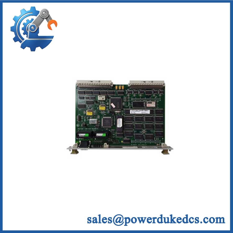
GE WESDAC D20ME II
Quality Assurance SOP
The II should be tested as a processor board with configurable communications hardware, not treated as a simple passive spare.
- OEM anti-counterfeit visual inspection: Verify GE identification, WESDAC II markings, board labeling, connectors, component condition, visible revision information, and evidence of unauthorized rework.
- Hardware configuration inspection: Record the complete board identification and determine whether the unit is the 526-2006 non-VME or 526-2007 VME variant.
- Power-on self-test (POST): Install the processor in a suitable D20/ test chassis, apply the specified supply, and observe the available FAIL, HALT, and RUN status indicators during initialization.
- WESMAINT verification: Connect through the maintenance interface and confirm that the processor reaches the expected service or monitor interface without startup faults.
- Communication handshake verification: Test representative RS-232 and RS-485 channels where the test fixture permits, confirming port initialization and expected data exchange.
- Memory verification: Execute a controlled memory diagnostic or equivalent functional test covering the installed Flash, NVRAM, and SRAM resources.
- Configuration verification: Confirm operation with the applicable D20 Base or CCU Base environment and verify that the expected configuration can be loaded.
- VME verification: For 526-2007 units, confirm VME node addressing and master/slave configuration before final release.
- Sustained run test: Operate the module continuously under controlled conditions while monitoring for unexpected resets, communication errors, or thermal abnormalities.
- Final traceability: Record the exact part number, visible serial information where available, test results, photographs, inspection date, and packaging condition.
GE’s documentation establishes that II boards can use either D20 Base firmware or CCU Base firmware, with the appropriate selection made during Config Pro configuration. The same documentation also identifies the VME/non-VME distinction and the per-channel RS-232/RS-485 capability, making the complete board variant and software configuration more important than the generic “WESDAC II” description alone.











 Start Chat


