

Description
- Brand — GE
- Full Model Number — WESTERM D20M++
- System/Series Family — GE D20/D200 RTU VME architecture
- Core Function — Rear termination panel providing VME-side interconnection, power termination, D.20 Link connections, and serial communications interfaces for D200 main processors
- Top 3 Hardcore Specs — Up to 4 D20ME/D20ME II boards per panel; up to 28 RS-232 serial ports; VME installation with ribbon-cable connections
- Stock Status — New Surplus / availability to be confirmed against physical inventory
Technical Product Introduction
Replacing a WESTERM panel in an older D200 cabinet is not the same task as replacing an ordinary terminal block. The GE WESTERM D20M++ is the termination interface used with the D200 VME architecture. GE documentation identifies it as the D200 termination panel and states that up to four D20ME or D20ME II main boards can connect to one D20M++ panel. The panel carries ribbon-cable connections, D.20 Link interfaces, a grounding block, a power termination block, and banks of RS-232 communication ports for separate nodes.
The architecture also explains why an exact panel match matters. GE documentation identifies the WESTERM D20M++ VME termination-panel drawing as P/N 517-0245, while the D200 documentation describes the serial architecture as 28 RS-232 ports on the WESTERM arrangement. Power for the D20M++ is terminated through TB2, with terminals 1 and 2 used for input power from the WESDAC D20 power supply.
Application Scenarios & Field Realities
- In a substation RTU cabinet, the D20M++ sits behind the VME backplane rather than functioning as a front-access I/O card. Ribbon cables establish the electrical path between the VME backplane and the termination panel, so cable routing and panel orientation should be documented before removal.
- When several D20ME or D20ME II processors are installed, one WESTERM ++ can support up to four main boards. Sites exceeding four main boards may require another termination panel, and GE also identifies cases where a second panel is needed when more than 28 serial ports are required.
- For legacy serial communications, the panel provides banks of RS-232 communication interfaces for separate nodes. That makes connector identification important during a swap; moving a cable to the wrong communication position can change which node is connected even though the replacement panel itself is correct.
- During scheduled maintenance, verify the installed main-processor count, VME backplane arrangement, ribbon-cable routing, grounding connection, and TB2 wiring before removing the original panel. A photographed termination layout is useful insurance during reassembly.
Migration Compatibility & Installation Traps
| Replacement Case | Classification | Engineering Guidance |
|---|---|---|
| Same WESTERM ++ assembly with matching VME arrangement | Drop-in Replacement | Appropriate when the installed chassis, panel revision, ribbon cables, and wiring configuration match. |
| WESTERM + substituted for ++ | Hardware Modification Required | + and ++ serve different D20/ chassis arrangements and should not be treated as interchangeable termination panels. |
| ++ retained while ++ main processors are replaced with /ME II | Software Compatible | GE documentation states that /ME II are backward compatible with ++ applications and use the same chassis architecture, but configuration and firmware must still be checked before commissioning. |
Field Traps — Watch Out
TB2 power identification: GE specifies the WESTERM ++ power connection on TB2, with terminals 1 and 2 used for input power based on the WESDAC D20 power supply. Never assume the power-terminal arrangement from a + panel applies to a ++.
Ribbon-cable and node mapping: The ++ is mounted behind the VME bus backplane and uses ribbon-cable connections. Record each cable position before replacement. The panel may physically fit while an incorrectly restored cable mapping leaves the associated processor or serial node unavailable.
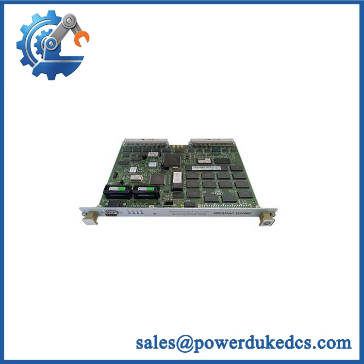
GE WESTERM D20M++
Quality Assurance SOP
For New Surplus GE WESTERM ++ inventory, inspection should focus on the termination hardware and its interfaces rather than treating the panel as an ordinary passive board:
- OEM anti-counterfeit visual inspection — Verify GE identification markings, WESTERM ++ designation, visible assembly information, connector style, PCB condition, terminal blocks, mounting hardware, and evidence of board-level rework.
- Power-on interface inspection — Verify TB2 terminal condition, connector integrity, grounding hardware, and expected power distribution in an approved test arrangement before applying system power.
- VME and ribbon-cable verification — Check each ribbon connector for damaged pins, locking features, contamination, and mechanical deformation; verify the interface against the intended backplane configuration.
- Communication handshake verification — Where a compatible test system is available, verify representative RS-232 node communication and D.20 Link initialization through the installed processor arrangement.
- Multi-processor verification — For configurations using multiple / II boards, confirm that the termination-panel connections correspond to the intended processor nodes.
- Traceability record — Photograph the front and rear interfaces, record all visible part and revision markings, document test observations, and retain the inspection record with the shipment.
- Final ESD and packing inspection — Protect exposed PCB areas and connectors, immobilize the panel inside ESD-safe packaging, and inspect the packed assembly before dispatch.
The key procurement reference is the WESTERM ++ VME termination architecture, with GE documentation identifying P/N 517-0245 for the corresponding module-layout drawing. Matching the panel to the existing backplane, processor count, ribbon-cable arrangement, and TB2 wiring is more important than relying on a generic “D20 termination panel” description.











 Start Chat


