Description
-
Brand: Honeywell
-
Full Model Number: FC-
-
Lifecycle Status: Legacy hardware; current OEM lifecycle status requires confirmation
-
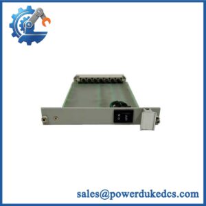
Core Function: Eight-channel safe digital output module for Honeywell Safety Manager systems; conformal-coated version
-
Top 3 Technical Specs: 24 VDC outputs; 550 mA maximum per channel; eight solid-state output channels
-
Stock & Condition: Physical stock, revision, condition, testing status, and dispatch date subject to written confirmation
Obsolescence & Supply Chain Deep Dive
A failed safety output module can extend an unplanned shutdown when an exact replacement is difficult to source. The Honeywell FC- is an eight-channel, 24 VDC safe digital output module designed for Safety Manager installations. Its conformal-coated construction is a key selection factor when replacing existing hardware in demanding environments. Unlike an ordinary digital output card, this module forms part of a safety-related control architecture, so matching the model number alone is insufficient. Verify the hardware revision, approved system configuration, field termination assembly, and applicable technical notices before committing to a purchase (actual replacement lead time depends on verified stock and export readiness).
For a confirmed compatible replacement, retaining the existing Safety Manager platform can avoid the engineering, wiring, validation, and commissioning expenses associated with a complete system migration. The relevant total cost of ownership (TCO) calculation includes the module price, maintenance labor, functional testing, outage exposure, and any additional engineering required for revision differences. A replacement that arrives quickly but fails configuration checks can increase downtime rather than reduce it. Request the actual unit’s identification-label photographs, revision details, condition statement, and agreed testing records before releasing the purchase order. Final acceptance must include the site-required functional and safety checks.
Compatibility & Replacement Matrix
|
Replacement Scenario |
Classification |
Required Action |
Budgetary Time Allowance |
|---|---|---|---|
|
Exact FC- model and approved hardware revision |
Conditional drop-in replacement |
Verify the rack, approved configuration, termination assembly, wiring, and replacement procedure. |
Approximately 2–4 maintenance labor hours for replacement and preliminary checks |
|
Different FC- hardware revision |
Engineering approval required |
Check the applicable Safety Manager release, module revision, configuration support, and technical notices. Do not assume a firmware flash is necessary. |
Approximately 2–4 engineering hours for an initial compatibility review |
|
FS- or another digital output module proposed as a substitute |
Not an automatic replacement |
Review the construction variant, environmental requirements, electrical ratings, hardware configuration, and safety documentation. |
Estimate after engineering review |
|
Replacement requiring terminal, wiring, or configuration changes |
Potential hardware or engineering modification |
Review drawings, termination hardware, field circuits, and commissioning requirements before authorizing the work. |
Site-specific estimate required |
Cost estimate: For a verified like-for-like replacement, budget the module price plus 2–4 hours of maintenance labor and the cost of required functional testing. Calculate labor costs using the site’s actual hourly rate. Additional engineering, outage time, or hardware changes must be estimated separately; these allowances are planning estimates, not guaranteed completion times.
Field Traps to Check Before Ordering
-
Conformal coating: FC- and FS- are distinct construction variants. Confirm the exact installed model and environmental requirements before accepting a substitute.
-
Output loading: Each channel has a documented maximum output current of 550 mA, but permissible loading depends on the specific load characteristics and operating conditions. Check lamp inrush, load capacitance, conductor ratings, and field-supply protection against the applicable hardware documentation.
-
Termination and wiring: Confirm the approved field termination assembly, interface cable, terminal allocation, and supply polarity. Similar model names do not establish electrical or mechanical interchangeability.
-
Safety validation: A successful module power-on test does not establish that the complete safety function is operational. Follow the approved site replacement procedure and complete the required functional tests before returning the circuit to service.
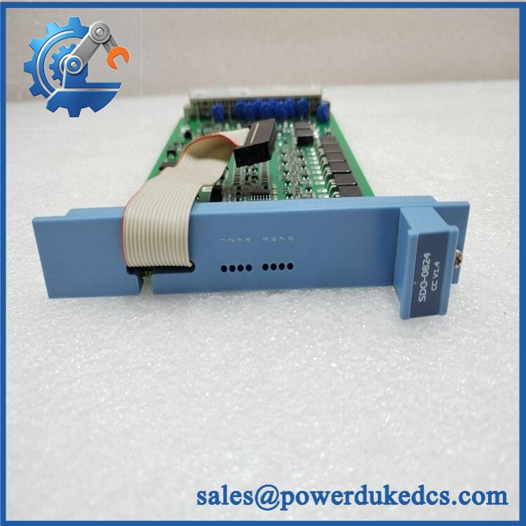
Honeywell FC-SDO-0824
Quality Assurance & Testing SOP
Every FC- offered for purchase should have an agreed inspection and acceptance scope. The following procedure describes the checks to request and document; individual tests must be performed only with suitable equipment and approved instructions.
Visual Inspection and Traceability
-
Model verification: Match the manufacturer label, complete part number, hardware revision, and conformal-coated designation against the purchase order.
-
Physical examination: Inspect the enclosure, connectors, contacts, and accessible surfaces for corrosion, contamination, impact damage, or signs of unauthorized repair.
-
Authenticity screening: Conduct an OEM anti-counterfeit visual inspection covering label consistency, markings, and available traceability records.
-
Photographic evidence: Capture the actual module and identification label before packaging. Do not rely solely on representative product images.
-
Condition declaration: Record whether the unit is new original, new surplus, or previously used, as applicable. Document the actual condition without relying on the label alone.
Power-On and Diagnostic Checks
-
Use an approved test fixture and the applicable hardware procedure to perform a controlled power-on self-test (POST).
-
Verify the module’s system recognition and record all applicable status indicators, including RUN or ERR indications where fitted and documented for the specific revision.
-
Review available diagnostic information and investigate unexplained fault indications before releasing the unit.
-
Confirm the test supply, grounding, termination, and connection arrangements match the approved test procedure.
-
Record the test date, equipment used, observed results, and any limitations.
Output Channel and Load Testing
-
Exercise all eight output channels using an approved test configuration and loads within the documented electrical limits.
-
Verify commanded output switching, de-energized behavior, and applicable fault diagnostics.
-
Check output response under representative approved loads without exceeding channel-current, lamp-load, or capacitance limits.
-
Test applicable safety-related output behavior using the approved procedure and qualified personnel.
-
Record individual channel results. A single successful power-on test is insufficient evidence of correct operation across all eight outputs.
Final Release and Documentation
-
Match the tested unit’s identification details to the sales documentation.
-
Provide the agreed inspection records, available test results, and actual-unit photographs.
-
Disclose any tests that were not performed and any limitations of the bench-test setup.
-
Package the module to protect it against electrostatic discharge, mechanical damage, and moisture exposure appropriate to its construction.
-
Release the unit only after the agreed acceptance criteria are satisfied.
Important: Bench testing supports an assessment of the supplied module; it does not replace site commissioning, proof testing, or validation of the complete safety instrumented function.
Procurement & Lifecycle FAQ
Is the Honeywell FC- in stock, and what is the emergency shipping cutoff?
Availability must be confirmed against the actual warehouse inventory. The quotation should identify the quantity available, unit condition, hardware revision, warehouse location, and earliest dispatch date. Emergency shipping depends on payment clearance, export documentation, packaging, and carrier collection schedules. Same-day dispatch requires explicit confirmation.
How do you verify authenticity and the condition of surplus modules?
Request actual-unit photographs, identification-label details, available traceability documents, and a written condition declaration. Where functional testing is required, specify the inspection scope and acceptance criteria in the purchase order. Confirm which test records will accompany the shipment. Visual inspection alone cannot establish functional performance.
Are firmware or hardware compatibility issues likely?
Compatibility depends on the installed Safety Manager configuration, hardware revision, termination arrangement, and applicable release documentation. Do not authorize an alternative revision based only on a matching model prefix. Ask the responsible controls or functional-safety engineer to approve the proposed unit before installation. Any firmware or configuration changes must follow the applicable OEM instructions.
What warranty and return terms apply?
Warranty coverage and return eligibility must be confirmed in writing before the purchase order is released. Establish the warranty duration, commencement date, defect-reporting deadline, return authorization procedure, and exclusions. Also clarify responsibility for return freight and the remedy available for a verified defective-on-arrival unit.
Can the FC- replace the FS-?
Not automatically. The FC- is the conformal-coated variant, while the FS- is a distinct construction variant. Confirm the environmental requirements, approved system configuration, electrical specifications, h