

Description
- Brand Motorola
- Full Model Number 01-W3839F-07A
- System/Series Family MVME2400 Series / MVME2434-1 VMEbus processor platform
- Core Function 6U VMEbus single-board computer for embedded control and industrial computing
- Top 3 Hardcore Specs 350 MHz PowerPC 750 | 256 MB ECC SDRAM | 6U VMEbus with two PMC slots
- Stock Status New Surplus — verify board revision, handles, faceplate, and configuration before shipment
Module 3: Technical Product Introduction
When a legacy VME control platform loses its processor board, replacing the CPU with a visually similar VME card is rarely enough. The Motorola 01-W3839F-07A is associated with the MVME2434-1, a 6U VMEbus processor module built around the 350 MHz PowerPC 750 and 256 MB ECC SDRAM. Motorola’s MVME2400 reference documentation lists the MVME2434-1 at 350 MHz with 256 MB ECC memory, while current technical references cross-reference 01-W3839F 07A directly to the MVME2434-1.
For an aging VME chassis, the architecture is still the key compatibility check. The MVME2400 design provides VMEbus system-controller capability, a 64-bit PCI local interface, one front-panel asynchronous serial port, 10/100Base-TX Ethernet, a watchdog timer, battery-backed RTC/NVRAM, and two PMC positions for expansion. The processor uses 1 MB of backside L2 cache, while the 256 MB ECC configuration provides single-bit error correction and double-bit error detection across the memory path.
Module 4: Application Scenarios & Field Realities
- Inside a legacy VME industrial controller, the MVME2434-1 can act as the central processor board while retaining the existing VMEbus backplane and installed peripheral cards. That makes it particularly relevant where a full chassis redesign would require extensive application migration work.
- For systems using PMC expansion, the two IEEE P1386.1-compatible PMC positions provide room for additional I/O or communication hardware. Before installing a spare, verify whether the existing application uses one or two PMC cards and confirm the exact carrier/connector arrangement.
- Where deterministic embedded control matters, the 350 MHz MPC750/PowerPC 750 architecture provides a considerably different processing environment from modern x86-based industrial computers. Software compatibility is therefore tied to the existing BSP, operating system image, boot configuration, and application binaries—not simply to the physical VME slot.
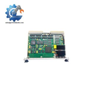
- During emergency VME system recovery, the exact assembly condition deserves attention. One current technical listing identifies 01-W3839F 07A as an MVME2434-1 fitted with 256 MB ECC SDRAM and Scanbe handles, while another listing shows that handle and faceplate configurations can differ. Confirm the physical configuration against the installed chassis before shipment.
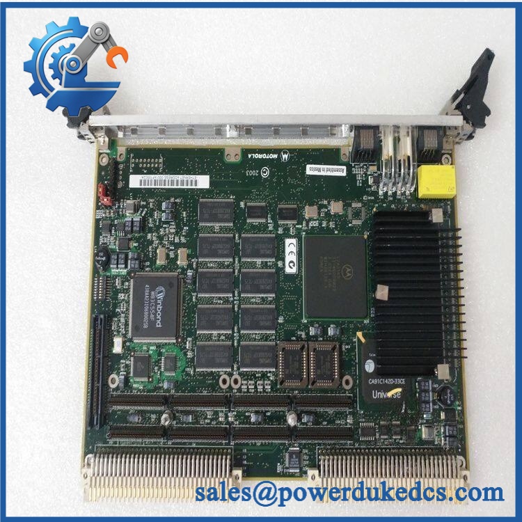
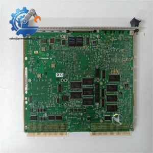
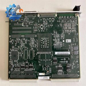
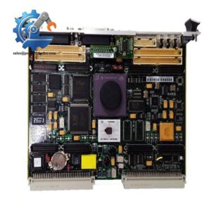
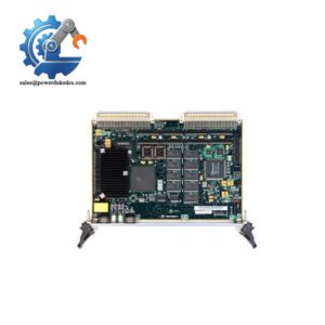
Motorola 01-W3839F-07A MVME2434-1
Module 5: Migration, Compatibility & Installation Traps
Replacement Matrix
| Replacement Status | Engineering Assessment |
|---|---|
| Drop-in Replacement | Yes, for a like-for-like installation using the same approved board configuration, VME backplane, PMC hardware, and software image. |
| Software Compatible | Generally yes for an exact board replacement, but the installed boot firmware, BSP, OS image, NVRAM settings, and application software must be preserved and verified. |
| Hardware Modification Required | Normally no for an exact 01-W3839F-07A / replacement. Modification may be required when moving between different MVME243x variants, PMC configurations, or VME system architectures. |
⚠️ Field Traps: Watch Out
Do not treat 01-W3839F-07A as a generic VME CPU. Cross-reference evidence associates this marking with the , specifically the 350 MHz / 256 MB ECC configuration. The MVME2430-series family includes several memory and processor variants, so the board identification must match the existing application baseline.
NVRAM and battery-backed configuration matter. The MVME2400 architecture includes battery-backed RTC/NVRAM and a watchdog timer. During replacement, record the existing configuration before removing the processor board, particularly when the application relies on stored boot parameters or board-specific settings.
Check the PMC configuration before inserting the spare. The board provides two PMC positions, but an installed application may depend on specific mezzanine hardware. A processor replacement that changes the PMC arrangement can create secondary I/O or boot problems even when the VME interface itself comes up correctly.
Do not mix memory variants without checking the software baseline. Motorola documentation distinguishes the MVME2431, MVME2432, MVME2433, and MVME2434 by memory capacity; the is the 256 MB ECC version.
Module 6: Quality Assurance SOP
A surplus should undergo board-level inspection plus a controlled VME system test. A successful power-on alone does not prove suitability for a legacy control application.
- OEM anti-counterfeit visual inspection: Verify Motorola markings, identification, designation where present, PCB revision, connector geometry, handles, faceplate, and board labeling against controlled reference documentation.
- Part-number and traceability check: Record the complete assembly number, board revision, serial number, memory configuration, and all available date or manufacturing codes.
- Mechanical inspection: Examine the VME P1/P2 connectors, PMC connectors, front-panel hardware, Scanbe/handle assembly, ejector mechanisms, heatsink, and PCB for bent contacts, cracks, corrosion, contamination, or unauthorized modifications.
- Power-on self-test (POST): Install the board in a known-good MVME2400-compatible VME test chassis and verify normal startup, board-fail indication, processor initialization, and expected diagnostic behavior.
- Memory verification: Run a controlled ECC SDRAM test across the installed 256 MB configuration, checking for address errors and memory instability.
- VMEbus verification: Confirm correct slot recognition, system-controller behavior where applicable, VME address-space access, and representative master/slave transactions.
- Ethernet verification: Test the front-panel 10/100Base-TX interface for link establishment, packet transmission, reception, and sustained traffic without errors. The MVME2400 reference documentation identifies the Ethernet interface as 10Base-T/100Base-TX.
- Serial-interface verification: Test the front-panel asynchronous serial port using controlled loopback and representative baud-rate configurations.
- PMC verification: Where the board is supplied with its intended PMC hardware, verify enumeration and functional data exchange for each installed PMC position.
- Watchdog verification: Confirm the watchdog function operates as expected under the approved test procedure rather than disabling or bypassing it during evaluation.
- RTC/NVRAM verification: Check clock retention and NVRAM read/write behavior while documenting battery condition. The architecture uses battery-backed RTC/NVRAM.
- Boot and operating-system verification: Load or boot the customer’s approved software environment where authorized and confirm successful startup, device enumeration, and application-level operation.
- Communication handshake verification: Verify Ethernet and VME communication through the actual installed control environment or a representative laboratory configuration; a simple link LED check is not sufficient.
- Thermal and extended-run test: Operate the board under representative processor, memory, Ethernet, VME, and PMC loading while monitoring for abnormal temperature rise, crashes, bus errors, or intermittent resets.
- Final QC record: Document board revision, memory size, POST results, VMEbus test, Ethernet and serial test results, PMC configuration, watchdog status, NVRAM/RTC condition, extended-run observations, traceability information, and packaging status.
Technical Identification Note: The supplied designation PCE I 01–07A requires careful catalog normalization. Multiple technical references cross-reference to the Motorola VME Processor Module, specified with a 350 MHz PowerPC 750 and 256 MB ECC SDRAM. Other secondary listings describe the same board inconsistently as an “AP-4” or communication module. For procurement and replacement control, the physical board identification and hardware baseline should take precedence over those inconsistent descriptions.



 Start Chat


