

Description
- Brand: MOTOROLA
- Full Model Number: C73249-A50-L10-3 05-A1-B
- System/Series Family: Motorola/Tektronix telecom test and protocol-analysis hardware family; exact host platform requires verification
- Core Function: Board-level telecom protocol test and analysis hardware
- Top 3 Hardcore Specs: C73249-A50-L10-3 board code; 05-A1-B variant; PCB/board-level assembly
- Stock Status: Verify current New Surplus, Factory Sealed, or Fully Tested Refurbished condition before order
Module 3: Technical Product Introduction
A replacement board in legacy telecom test equipment should never be identified from a generic industrial-module description alone. The MOTOROLA C73249-A50-L10-3 05-A1-B is presently indexed by multiple industrial automation sources as a Telecom Protocol Test Board, while another source describes the same part number as an industrial communication module. The stronger identifying evidence is the board-level test designation: a current Motorola product index classifies this exact number as a Telecom Protocol Test Board, and separate technical listings associate the C73249 family with Tektronix communications test equipment.
That distinction matters during procurement. The available evidence does not provide a reliable primary-source electrical datasheet for this exact C73249-A50-L10-3 05-A1-B variant, so values such as supply voltage, Ethernet or serial interfaces, current draw, operating temperature, dimensions, and weight should not be copied from generic industrial communication-module listings. One reseller publishes 12 VDC, RS485, Ethernet, MQTT, and DIN-rail specifications, but those details conflict with the board-level telecom-test identification and should therefore be treated as unverified rather than as engineering specifications.
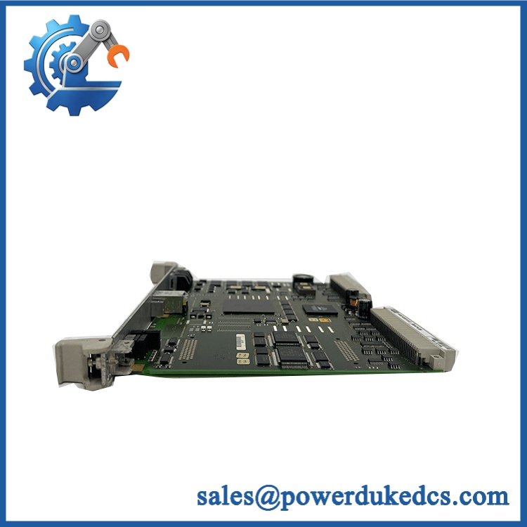
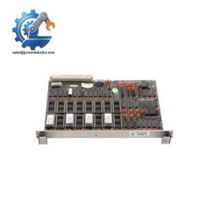
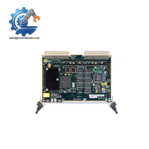
MOTOROLA C73249-A50-L10-3 05-A1-B
Module 4: Application Scenarios & Field Realities
- Inside legacy telecom protocol-analysis equipment, the C73249 assembly is best treated as a board-level test-system component rather than a standalone DIN-rail communications device. Host chassis compatibility, mating connectors, firmware revision, and installed option configuration should be confirmed before replacement.
- During maintenance of older communications test platforms, the complete identification string matters. The base C73249 number is accompanied by the A50-L10-3 construction code and the 05-A1-B variant marking; record the full label before removing the original assembly.
- For bench-level protocol testing, the board may form part of a larger test instrument rather than acting as an independent field controller. Do not connect field power or network cables based solely on third-party catalog descriptions; follow the host instrument drawing and connector pinout.
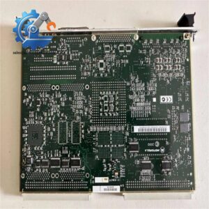
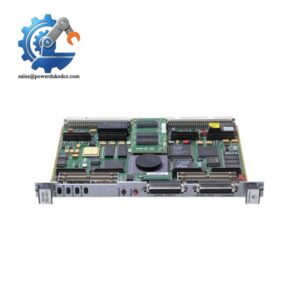
- When sourcing a discontinued spare, photographs of the actual PCB, connector layout, revision markings, and host-equipment model can be more useful than a generic part-number match. Current public listings confirm that the family appears across legacy telecom/communications test hardware, including Tektronix-related equipment.
Module 5: Migration, Compatibility & Installation Traps
Replacement Matrix
Exact -A50-L10-3 05-A1-B assembly with matching host equipment: Drop-in Replacement
Use this classification only when the board revision, connector arrangement, host chassis, firmware requirements, and installed options match the original unit.
Same family with different suffix or revision: Software Compatible / Hardware Verification Required
A similar code does not establish electrical or functional equivalence. Compare PCB revision, connector population, option code, firmware compatibility, and host-instrument documentation before substitution.
Generic industrial communication module substituted for -A50-L10-3: Hardware Modification Required
This is not an acceptable direct replacement merely because a third-party listing assigns RS485, Ethernet, or other communications functions to the part. The available evidence identifies the exact requested assembly as a telecom protocol test board.
⚠️ Field Traps (Watch Out)
Catalog-identity trap: The exact part number is described inconsistently across commercial sources. One source calls it an industrial communication module with DIN-rail mounting and 12 VDC power, while another identifies it as a telecom protocol test board. Those descriptions cannot safely be treated as equivalent engineering data.
Host-platform trap: A board-level assembly should be matched to the equipment in which it was originally installed. Check connector keying, slot position, neighboring boards, firmware requirements, and chassis documentation before applying power.
Module 6: Quality Assurance SOP
Pre-Shipment QA Protoc MOTOROLA 05-A1-B
- Step 1 — Identity Verification: Confi complete 05-A1-B marking, board revision, serial information where available, manufacturer label, and any host-equipment identification.
- Step 2 — OEM Anti-Counterfeit Visual Inspection: Examine PCB markings, component references, labels, date codes, connector bodies, fasteners, solder workmanship, and evidence of unauthorized component replacement.
- Step 3 — Mechanical Inspection: Inspect the PCB for edge damage, cracked solder joints, bent connectors, corrosion, contamination, board warpage, and damaged mounting hardware.
- Step 4 — Component-Level Visual Check: Review high-risk components such as power regulators, crystals/oscillators, interface transceivers, socketed devices, and electrolytic capacitors for discoloration, leakage, swelling, or rework.
- Step 5 — Controlled Power-On: Apply power only through the verified host equipment or an approved engineering test fixture. Do not use the 12 VDC figure published by an unverified reseller as the test voltage.
- Step 6 — POST / Status Verification: Check host-equipment startup behavior, board recognition, diagnostic indicators, and any reported hardware faults.
- Step 7 — Communication Handshake Verification: Where the original host platform supports it, confirm that the installed board is recognized and that the expected test-system communication path initializes correctly.
- Step 8 — Functional Test: Run the approved telecom protocol or signal-path diagnostic for the host instrument. Record pass/fail results rather than relying on visual power-up alone.
- Step 9 — Thermal and Stability Check: Operate the board under representative test conditions and monitor abnormal heating, intermittent resets, connector instability, or communication errors.
- Step 10 — Final QC Record: Record the complete part number, board revision, host-equipment model, test procedure, diagnostic results, visual condition, test date, and final QC disposition.
Technical Verification Note: Public evidence supports identifying MOTOROLA 05-A1-B as a telecom protocol test board, while some commercial databases incorrectly or inconsistently characterize it as a generic industrial communication module. No authoritative primary-source datasheet for the exact suffix was located in the available public evidence. For procurement and replacement decisions, the physical nameplate, PCB revision, host-equipment model, and original equipment documentation should therefore take precedence over generic reseller specifications.



 Start Chat


