

Description
- Brand: PROVIBTECH
- Full Model Number: TM521-A02-B00-C02-D00-E01-G00-I0-M1
- System/Series Family: TM521 vibration monitoring / transmitter family
- One-Sentence Core Function: Industrial vibration measurement and signal transmission for rotating equipment condition monitoring
- Top 3 Hardcore Specs: Configured A02 / C02 / E01; vibration measurement transmitter; order-code-specific configuration
- Stock Status: Stock condition and exact hardware revision to be confirmed before shipment
Module 3: Technical Product Introduction
A vibration-monitoring replacement is rarely judged by the enclosure alone. The critical question is whether the sensing, signal conditioning, output configuration, and mechanical installation match the existing monitoring loop. The exact TM521-A02-B00-C02-D00-E01-G00-I0-M1 order code is identified in available references as a PROVIBTECH vibration monitoring module/transmitter. It is intended for converting machinery vibration information into signals usable by plant monitoring or control equipment.
The published configuration reference describes the TM521 as an industrial vibration transmitter family and identifies versions with multiple output and measurement configurations. However, the available evidence does not provide a manufacturer-grade decoding table for every letter-number option in the exact A02-B00-C02-D00-E01-G00-I0-M1 suffix. For that reason, voltage, current output, measurement range, sensor type, and enclosure rating should be verified from the nameplate or original datasheet before treating those values as purchase specifications. This distinction matters when replacing a field transmitter already wired into a DCS, PLC, or machinery protection circuit.
Module 4: Application Scenarios & Field Realities
- On compressor trains, vibration transmitters are commonly installed where machinery condition data must reach the control or monitoring system as an engineering signal. Before replacement, confirm whether the existing loop expects an analog vibration value, a digital interface, or a dedicated machinery-monitoring input.
- For centrifugal pumps and motor-driven rotating equipment, the practical issue is signal compatibility rather than simply matching the model number. Check sensor technology, engineering units, output scaling, and loop power requirements against the existing cabinet drawings.
- Around fans, gearboxes, and other rotating assets, installation geometry can materially affect the measurement. A mechanically equivalent transmitter with a different sensor configuration may produce a perfectly valid electrical output while still delivering the wrong vibration parameter.
- During an emergency spare swap, photograph the existing wiring, connector orientation, range markings, and configuration label before removing the failed unit. The exact TM521 suffix contains multiple configuration fields, so replacing it by the short family name alone is not sufficient.
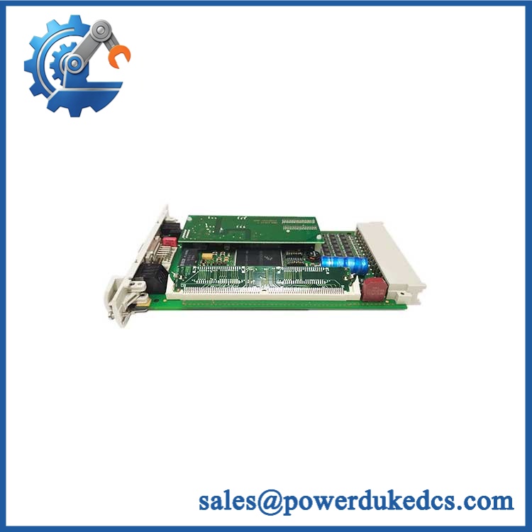
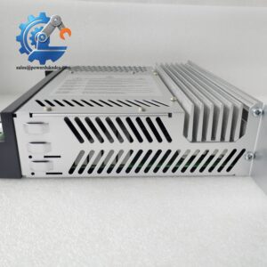
PROVIBTECH TM521-A02-B00-C02-D00-E01-G00-I0-M1
Module 5: Migration, Compatibility & Installation Traps
Replacement Matrix
Replacement Classification: Software Compatible / Configuration-Matched Replacement — Verify Exact Option Code Before Installation
This exact TM521 order code should not be classified as a universal drop-in replacement for every unit. The long ordering string indicates a configured product, and available references show that the TM-series contains multiple variants with different sensing and interface arrangements. A replacement is acceptable only when the complete ordering code, electrical interface, sensor arrangement, and mounting configuration match the installed unit.
No firmware flash or control-logic recompilation should be assumed merely from the model designation. The more immediate compatibility checks are electrical scaling, output type, sensor input, supply voltage, terminal assignment, and the engineering-unit configuration expected by the receiving system.
⚠️ Field Traps — Watch Out
1. Exact suffix mismatch: Do not substitute a shorter designation for the complete A02-B00-C02-D00-E01-G00-I0-M1 configuration. TM-series references show numerous option-code combinations, and apparently minor suffix changes can represent different hardware configurations.
2. Signal-loop mismatch: Confirm the existing receiving channel before energization. A transmitter configured for a different output or vibration parameter can produce a signal that looks electrically normal while reporting the wrong engineering value. For a live DCS or machinery-monitoring loop, verify scaling at the cabinet and transmitter ends before returning the asset to service.
Module 6: Quality Assurance SOP
Each unit should be released only after the complete ordering code and electrical configuration have been recorded.
- OEM identification visual inspection: Verify the manufacturer marking, complete ordering code, nameplate information, serial number, connectors, housing, and visible PCB or terminal markings.
- Configuration verification: Record the complete -A02-B00-C02-D00-E01-G00-I0-M1 code rather than documenting only “.” Photograph the nameplate for traceability.
- Mechanical inspection: Check mounting threads, connector interfaces, housing integrity, terminals, seals, and signs of impact, corrosion, or moisture ingress.
- Power verification: Apply only the supply specified for the exact configured unit and confirm stable startup behavior under the approved test procedure.
- Power-on self-test (POST): Verify status indication and startup behavior where the installed configuration provides diagnostic indicators.
- Signal-path verification: Inject an approved test input or use the applicable calibrated vibration test fixture, then compare the transmitter output against the expected response.
- Receiving-system handshake verification: Connect the unit to an appropriate test acquisition channel and confirm that the DCS, PLC, or monitoring interface receives a stable and correctly scaled signal.
- Output scaling check: Record zero-point and representative span-point measurements. Do not release a transmitter solely because its output changes; the engineering scale must also be correct.
- Final QC record: Retain photographs, serial number, full order code, supply-test result, signal-output readings, calibration/test observations, and QC approval.
For this part number, identification accuracy is the first QA gate. The available references associate the exact order code with PROVIBTECH, while the submitted brand was HIMA. That manufacturer mismatch should be resolved against the physical nameplate or original procurement record before the part is represented as a HIMA product.



 Start Chat


