

Description
- Brand: Triconex
- Full Model Number: 3301
- System/Series Family: Trident
- Core Function: 32-point commoned 24 VDC TMR digital input acquisition
- Top 3 Hardcore Specs: 32 digital input points; 24 VDC nominal; 15–30 VDC operating range
- Input Threshold: 0–5 VDC Off; 6–14 VDC transition; 15–30 VDC On
- Input Delay: <10 ms On-to-Off / Off-to-On
- ADC Scan Time: <1 ms for all 32 points
- Diagnostics: Force-to-value diagnostic (FVD)
- Isolation: 500 VDC functional-to-protective-earth; 800 VDC functional-to-functional-earth
- Hot Spare: Supported
- Baseplate: 2301 Digital Input Baseplate
- Logic Power: <3 W
- Stock Status: New Surplus or Fully Tested Refurbished; exact revision to be confirmed
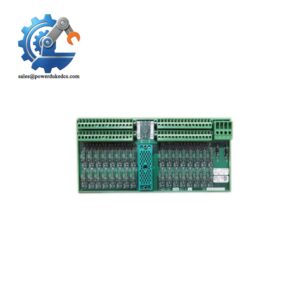
Triconex documentation identifies Model 3301 as the Trident Digital Input Module, with 32 commoned 24 VDC points. The module contains three independent electronic channels and supports hot sparing for online replacement.
Module 3: Technical Product Introduction
A digital status signal inside a safety controller is not just an ON/OFF value. The input electronics must detect the field state, check channel health, and maintain the TMR architecture when one internal path develops a fault. The Triconex 3301 is a 32-point commoned digital input module for the Trident safety controller. Its three independent channels process the field data separately, while the Main Processors receive and vote the resulting input information. Triconex also specifies continuous diagnostics and hot-spare support, allowing a failed module to be replaced while maintaining the controller architecture when the applicable maintenance procedure is followed.
The electrical figures are well defined. Each point uses a 24 VDC nominal input, with a 15–30 VDC operating range and 33 VDC absolute maximum. The input thresholds are 0–5 VDC for Off, 6–14 VDC as the transition region, and 15–30 VDC for On. Input delay is below 10 ms, while the ADC scans all 32 points in less than 1 ms. The module also performs force-to-value diagnostics, with a specified test time below 2 ms, and provides at least 500 VDC functional-to-protective-earth isolation and 800 VDC functional-to-functional-earth isolation.
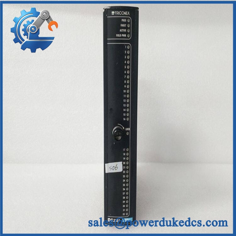
TRICONEX 3301
Module 4: Application Scenarios & Field Realities
- For ESD and shutdown status monitoring, the 3301 can acquire 24 VDC field contacts such as permissive switches, limit switches, trip relays, and equipment status contacts. The three-channel architecture allows the same field point to be processed through independent electronic paths before the control system votes the result.
- Where online maintenance is required, the module’s hot-spare capability is especially useful. The active and spare modules occupy the paired positions on the Trident I/O baseplate, with the controller able to transfer control when the active module develops a fault.
- On cabinets with long-running 24 VDC status circuits, the input threshold must be considered at the actual module terminals, not only at the field device. Voltage drop in cable, terminal resistance, or contact degradation can push a marginal signal into the 6–14 V transition region instead of a definite logic state. The documented transition region is therefore important during loop testing.
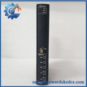
- During troubleshooting of a suspicious input channel, the front-panel PASS, FAULT, ACTIVE, FIELD PWR, and individual point indicators provide useful first-level evidence. A FAULT indication does not automatically mean that the entire module has failed; Triconex documentation states that diagnostics identify channel faults as well.
Module 5: Migration, Compatibility & Installation Traps
Replacement Matrix
Replacement classification: Drop-in Replacement when the existing installation is a compatible Trident 3301 configuration using the correct 2301 digital-input baseplate, field wiring, and system configuration.
Software compatibility: Configuration verification required. The 3301 itself is an I/O hardware module, but its channel definitions, system configuration, diagnostics, and hot-spare arrangement must correspond to the existing Trident application.
Cross-model replacement: Hardware modification or engineering verification required. A different Triconex digital-input module may have different voltage ranges, channel counts, baseplates, termination methods, or diagnostic behavior. A similar front-panel appearance does not establish equivalence.
Field Traps — Watch Out
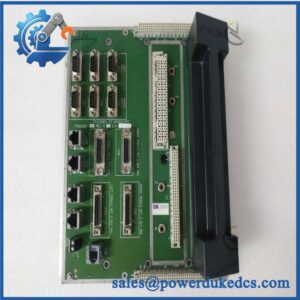
1. Match the 2301 baseplate. Triconex documentation identifies Model 2301 as the Digital Input Baseplate associated with the 3301. The baseplate provides the field termination and dual field-power paths, so a 3301 should not be installed into an unrelated I/O baseplate without documented compatibility.
2. Do not treat 6–14 VDC as a valid steady-state logic level. That range is explicitly identified as the transition region. During commissioning, a field circuit that measures 8 or 10 V at the module should be investigated rather than accepted as a reliable ON or OFF state.
3. Verify field-power conditions before diagnosing the module. The 3301 is a 24 VDC digital input device, and the associated baseplate provides field-power connections. A weak or interrupted field supply can create multiple apparent input faults that are actually downstream of the module electronics.
4. Preserve the hot-spare arrangement. The Trident I/O architecture supports paired active and spare positions, and the module is mechanically keyed to prevent installation into an incorrect configured slot. Do not defeat the keying or relocate the module without following the approved maintenance procedure.
Module 6: Quality Assurance SOP
Pre-Shipment Inspection Protocol for TRICONEX 3301
- OEM identity inspection: Verify Triconex marking, exact model 3301, hardware revision, serial number, front-panel identification, and any additional assembly markings.
- Architecture verification: Confirm that the unit is the Trident 3301 Digital Input Module, not a visually similar Triconex processor or another I/O model.
- Mechanical inspection: Examine the housing, card-edge interfaces, locking mechanism, connector areas, LED indicators, and accessible PCB surfaces for corrosion, contamination, deformation, cracked components, or unauthorized repair.
- Baseplate verification: Install the module only in a compatible 2301 digital-input baseplate and confirm correct mechanical keying and seating.
- Power-on self-test: Energize the module in a controlled Trident test system using the documented 24 VDC logic and field-power architecture. Check PASS, FAULT, ACTIVE, and FIELD PWR indicators.
- Input threshold test: Apply calibrated DC input levels representative of the documented Off, transition, and On regions and confirm correct state recognition.
- 32-channel test: Exercise all 32 input points independently and record the response of every channel rather than qualifying the module from a single representative point.
- Input-delay verification: Apply controlled On-to-Off and Off-to-On transitions and verify response within the documented <10 ms input-delay requirement.
- ADC scan verification: Use the appropriate Trident test environment to verify correct acquisition of all 32 channels within the published scan behavior.
- Diagnostic verification: Exercise the force-to-value diagnostic path and verify that controlled fault conditions generate the expected diagnostic response without creating false healthy indications.
- Hot-spare test: Where the test bench permits, install an active/spare pair and verify controlled transfer between the active and spare module under the applicable Trident maintenance procedure.
- Isolation verification: Perform appropriate controlled isolation testing between field circuitry, protective earth, and logic circuitry using instruments and test voltages permitted by the applicable procedure.
- Thermal observation: Operate the module under representative 32-channel activity and monitor for abnormal temperature rise, intermittent channel states, diagnostic faults, or unstable field-power behavior.
- Final QC record: Record model, revision, serial number, test chassis/baseplate, supply measurements, all 32 channel results, diagnostic results, hot-spare result where applicable, test date, and inspector approval.
- ESD-controlled packaging: Place the module in an ESD-safe package and protect the locking mechanism, connectors, LED panel, and PCB surfaces against impact, moisture, contamination, and electrostatic discharge.
Procurement note: The technically supported identification is TRICONEX 3301 — Trident 32-point, 24 VDC TMR Digital Input Module. Officially documented characteristics include 32 commoned inputs, 15–30 VDC operating range, <10 ms input delay, <1 ms scan time for all 32 points, FVD diagnostics, hot-spare support, and 500/800 VDC isolation ratings. It should be matched with the appropriate 2301 Digital Input Baseplate and the existing Trident configuration.



 Start Chat


