

Description
- Brand: TRICONEX / Schneider Electric
- Full Model Number: 3361
- System/Series Family: Trident v1–v3
- One-Sentence Core Function: 32-point TMR hybrid input module combining 16 analog 4–20 mA channels with 16 digital 24 VDC channels
- Top 3 Hardcore Specs: 16 AI + 16 DI; 12-bit AI resolution; 15–30 VDC DI operating range
- Stock Status: Stock condition and hardware revision to be confirmed
Module 3: Technical Product Introduction
A mixed analog/discrete input requirement can consume valuable I/O positions when handled with separate modules. TRICONEX 3361 addresses that constraint with one Trident I/O module containing 32 commoned points: 16 digital inputs on points 1–16 and 16 analog inputs on points 17–32. The module uses three isolated electronic channels that independently process the field signals, transmit channel data to the three associated Main Processors, and rely on the Trident processors to vote the resulting data before it reaches the control application. It also supports the Trident hot-spare architecture.
The analog section accepts 4–20 mA DC, with a specified operating range of 2–22 mA, 12-bit resolution, 16 Hz 3 dB bandwidth, and 0.15% of full-scale absolute error at 20 mA. Its scan time is specified at less than 1 ms for all 32 points. The digital section uses a nominal 24 VDC input, operates from 15–30 VDC, and defines 0–5 VDC as Off, 6–14 VDC as the transition region, and 15–30 VDC as On. Digital input delay is specified at less than 10 ms.
Module 4: Application Scenarios & Field Realities
- In a turbine or compressor auxiliary system, the 3361 can collect transmitter currents and discrete equipment states from the same Trident I/O column. Keep the channel groups straight during commissioning: points 1–16 are digital, while points 17–32 are analog. A wiring error across that boundary can produce a confusing mix of invalid states and process readings.
- For pressure, flow, or level transmitters, the analog channels are specified around the 4–20 mA process-current standard. Because the module’s absolute error is stated as 0.15% of full scale at 20 mA, verify the transmitter loop, signal conditioner, and TriStation scaling together rather than treating the I/O card as the only source of measurement accuracy.
- On valve feedback, motor status, and permissive circuits, the 16 digital channels provide 24 VDC state detection with a defined transition region. Measure voltage at the actual I/O termination point; a nominal 24 VDC supply can fall into the 6–14 VDC transition range after cable resistance, contact degradation, or a weak field supply is introduced.
- During online maintenance, the 3361 is designed for the Trident hot-spare architecture and is mechanically keyed to prevent installation into an incompatible configured baseplate. The standard matching baseplate is Model 2361, while an external-termination baseplate is also supported. Verify the baseplate before releasing a replacement because the module and termination hardware form one field interface.
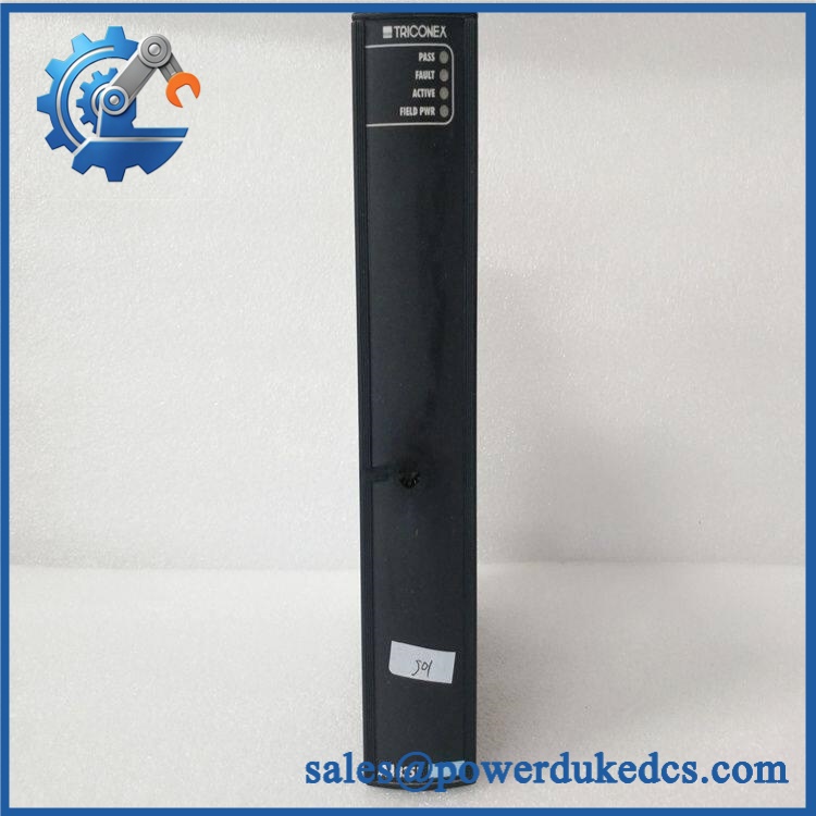
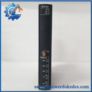
TRICONEX 3361
Module 5: Migration, Compatibility & Installation Traps
Replacement Matrix
Replacement Classification: Drop-in Replacement Within the Matching Trident 3361 / 2361 Configuration
A like-for-like TRICONEX 3361 replacement is suitable for an existing Trident installation when the module revision, application configuration, baseplate, termination arrangement, and system generation match. Trident documentation explicitly identifies the 5361 Analog Input/Digital Input TriPak as consisting of a 3361 module and 2361 AI/DI baseplate kit.
3361 → 3351: Hardware Modification Required. Model 3351 is an analog-input-only module with 32 analog points, while 3361 provides 16 digital and 16 analog points. Their channel assignments and field wiring are therefore different.
3361 → 3301: Hardware Modification Required. Model 3301 is a 32-point digital-input module. It cannot directly reproduce the 3361’s 16 analog channels, so substituting it changes both the I/O function and field interface.
⚠️ Field Traps — Watch Out
1. Channel-group mismatch: The 3361 is not a generic “32-channel input card.” Points 1–16 are DI, and points 17–32 are AI. Confirm every terminal against the approved wiring schedule before energization.
2. Analog loop limits: The analog section is specified for 2–22 mA operation, with 50 mA absolute maximum input current and 33 VDC absolute maximum field voltage. Do not inject a test current above the approved limit merely to prove the channel responds.
3. Digital threshold margin: The DI section defines 0–5 VDC as Off, 6–14 VDC as transition, and 15–30 VDC as On. A field signal sitting in the transition region should not be treated as a valid logic-high condition.
4. Baseplate dependency: The 3361 is compatible with the 2361 AI/DI baseplate and specified external-termination arrangements. Reusing another Trident I/O baseplate solely because the module physically fits can produce an incorrect field interface.
Module 6: Quality Assurance SOP
Each TRICONEX 3361 should pass a documented identification, analog-input, digital-input, and TMR diagnostic sequence before shipment.
- OEM identification visual inspection: Verify TRICONEX / Schneider Electric markings, 3361 designation, serial number, hardware revision, connector condition, module keying, and front-panel labeling.
- Platform verification: Confirm compatibility with the customer’s Trident generation and record the installed 2361 baseplate or approved external-termination arrangement.
- Mechanical inspection: Examine the housing, I/O connector, guide/keying features, PCB assembly, LEDs, mounting points, and visible components for cracks, corrosion, contamination, or previous repair.
- Power verification: Install the module in an approved Trident test chassis and apply the documented field supply conditions. The general Trident field supply specification is 24 VDC nominal, +19.2 to +30 VDC with specified AC ripple.
- Power-on self-test (POST): Confirm normal startup behavior, module status, fault indication, and expected TMR initialization.
- 16-channel analog test: Apply calibrated current sources to all 16 AI channels at representative low-, mid-, and high-range values and record the resulting values.
- 4–20 mA verification: Exercise representative channels around 4 mA, 12 mA, and 20 mA and compare measured values with the configured engineering scale.
- Analog accuracy check: Verify representative channels against the documented 0.15% full-scale absolute-error characteristic at the applicable test conditions.
- 12-bit resolution verification: Confirm that representative AI channels produce the expected digital response across the configured range.
- 16-channel digital test: Exercise points 1–16 with controlled 24 VDC signals and verify the expected Off, transition, and On behavior.
- Digital threshold verification: Test representative inputs around the documented 5 VDC and 15 VDC boundaries, ensuring the transition region is correctly recognized.
- FVD diagnostic test: Verify the Force-to-Value Diagnostic function using the authorized Trident maintenance procedure. The published diagnostic test time is less than 2 ms per test.
- TMR channel verification: Confirm that all three isolated processing channels correctly receive the AI/DI data and that processor voting delivers the expected result to the control application.
- Hot-spare verification: Where required, test the 3361 as a standby module in an approved Trident configuration and verify controlled replacement behavior.
- Extended stability test: Run representative AI and DI activity while monitoring channel status, fault indications, processor communications, and input stability.
- Final QC record: Retain complete part-number photographs, hardware revision, baseplate reference, all AI/DI test results, threshold measurements, FVD results, TMR verification, and final QC approval.
The TRICONEX 3361 is specifically a Trident TMR Analog Input/Digital Input module, not a conventional 32-channel analog card. Its defining replacement attributes are the 16-channel 4–20 mA AI section, 16-channel 24 VDC DI section, 12-bit analog resolution, sub-1 ms full-module scan, FVD diagnostics, three isolated processing channels, hot-spare support, and Model 2361-compatible baseplate architecture. The complete AI/DI channel assignment must be preserved when replacing the module in a live Trident installation.



 Start Chat


