

Description
- TRICONEX 4000094-310 | Factory Tested SIS Cable Assembly
2. At-A-Glance Executive Brief
- Model: TRICONEX 4000094-310
- Brand: TRICONEX (Schneider Electric / Invensys Tricon Safety System)
- Series: Tricon / Triconex Safety Instrumented System (SIS)
- Part Type: External Output Cable Assembly
- Core Function: Provides the electrical connection between Tricon controller chassis interfaces and external termination equipment.
- Key Specs:
- Cable assembly type: External output interface cable.
- Standard length reference: 10 ft (approximately 3 m).
- Used with Tricon safety system I/O termination arrangements.
- Supports connection between controller backplane interfaces and field termination components.
- Approximate shipping weight: 0.3–0.5 kg depending on packaging.
3. Product Introduction
Structure B — Technical Direct
Within a TRICONEX safety controller architecture, the 4000094-310 functions as an external interface cable assembly connecting Tricon chassis I/O interfaces to external termination panels. The cable does not execute control logic; instead, it provides the physical signal path required for reliable field wiring integration.
In field deployments, these assemblies remain installed for many years in refineries, power stations, and chemical facilities where Tricon SIS platforms operate continuously (—which makes cable condition a maintenance concern rather than a simple wiring replacement task). Verify connector keying, cable length, termination panel compatibility, and routing requirements before installation. A cable with the correct family number but incorrect interface configuration can create commissioning delays.
4. Core Technical Specifications
| Parameter | Value |
|---|---|
| Manufacturer | TRICONEX |
| Model Number | 4000094-310 |
| Product Type | External Output Cable Assembly |
| System Family | Tricon Safety Instrumented System |
| Cable Length | Approx. 10 ft / 3 m |
| Connection Type | Tricon chassis interface to termination equipment |
| Application | SIS I/O field interface connection |
| Installation Location | Control cabinet |
| Connector Type | Tricon-compatible keyed connectors |
| Operating Environment | Industrial automation cabinet |
| Voltage Rating | Application dependent |
| Shielding | Cable shielding according to system design |
| Approximate Weight | 0.3–0.5 kg |
| Packaging Requirement | ESD / protective cable packaging |
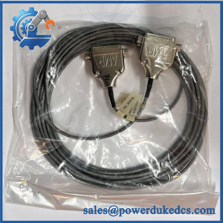
TRICONEX 4000094-310
5. Application Scenarios & Pain Points
Micro-case study approach:
A refinery maintenance team receives an intermittent I/O communication alarm from a Tricon safety cabinet. Diagnostics show that the controller and I/O modules remain healthy, but the field termination connection has unstable continuity. Inspection identifies degradation in the external interface cable assembly.
- Oil & Gas Facilities: Used in emergency shutdown (ESD) systems where reliable field signal transmission is required for valves, sensors, and trip devices.
- Chemical Processing Plants: Supports SIS cabinet wiring where cable integrity affects safety loop availability.
- Power Generation Units: Applied in turbine protection and auxiliary safety systems.
- Offshore Platforms: Requires careful inspection because vibration and salt exposure can affect connectors over long service periods.
- Legacy Tricon Installations: Maintains existing SIS infrastructure where complete cabinet replacement is not planned.
During cabinet maintenance, inspect cable routing when internal temperatures exceed 50°C. Heat exposure combined with vibration may accelerate insulation aging and connector stress.
6. Common Error Codes & Diagnostic Symptoms
Symptom/Code: I/O Communication Fault / Channel Diagnostic Alarm
→ Diagnosis: Damaged cable conductors, loose connectors, or poor termination contact may interrupt signal transmission between the Tricon chassis and field interface.
→ Action: Inspect cable continuity and replace the 4000094-310 assembly if cable failure is confirmed.
Symptom/Code: Intermittent Field Signal Loss
→ Diagnosis: Connector contamination, mechanical stress, or internal conductor damage may cause unstable connections.
→ Action: Perform continuity testing and replace the cable assembly.
Symptom/Code: Multiple Related I/O Points Fail Simultaneously
→ Diagnosis: A shared interface cable path may be affected rather than individual field devices.
→ Action: Check the interface cable before replacing I/O modules.
7. Cross-Reference & Lifecycle Migration
- System Compatibility: Designed for TRICONEX Tricon safety system interface applications.
- Related Identification: Frequently listed as an external output cable assembly for Tricon systems.
- Cable Length Variants: Tricon interface cable families may include different lengths depending on termination panel requirements. Confirm exact suffix before ordering.
- Firmware Requirement: None. This is a passive cable assembly and does not contain programmable logic.
- Lifecycle Status: Legacy / Active Installed Base Support
For spare stock planning, maintain cable assemblies by exact part number and length. A physically similar cable may not match connector pinout or termination requirements.
8. Field Engineer’s Tech Notes (Anti-Pitfall Guide)
- Do not assume any Tricon cable with matching connectors is interchangeable.
Check the termination panel model and cable suffix first. Pin mapping differences can create hidden I/O problems. - Protect connector ends during storage.
Keep dust caps installed and avoid placing heavy items on the cable coil. Connector damage is often discovered only during startup testing.
9. Strict QA & Testing SOP
A professional inspection process for TRICONEX 4000094-310 should include:
Step 1 — Incoming Inspection
- Confirm model marking: 4000094-310.
- Verify cable length.
- Inspect connector housings and keying features.
- Check insulation surface for cuts or deformation.
Step 2 — Electrical Verification
- Perform conductor continuity testing.
- Check for shorts between conductors.
- Verify connector pin assignment where documentation is available.
Step 3 — Mechanical Inspection
- Inspect strain relief areas.
- Check connector locking mechanisms.
- Confirm cable flexibility.
Step 4 — System Compatibility Review
- Match cable with Tricon chassis and termination panel.
- Verify installation documentation.
- Confirm replacement part number.
Step 5 — Packaging Control
- Coil cable without excessive bending stress.
- Protect connectors with covers.
- Use moisture-resistant export packaging.
Inspection photos, continuity test records, and test videos are available for verification.
10. Buyer’s FAQ (Dynamic Q&A)
Q1. Can the TRICONEX 4000094-310 be replaced while the SIS system is running?
A: No. Cable replacement should follow the approved maintenance procedure. Disconnecting an active safety system interface may affect monitored I/O signals.
Q2. “How do I confirm this is a New Original 4000094-310?”
A: Verify the part label, cable markings, connector condition, length specification, supplier traceability, and inspection records.
Q3. Does this cable require firmware or configuration loading?
A: No. The 4000094-310 is a passive cable assembly. Configuration resides in the Tricon controller and engineering system.
Q4. What warranty information should be requested?
A: Request written warranty terms, inspection confirmation, and condition classification such as New Original, New Surplus, or refurbished. Cable assemblies should be electrically tested before shipment.



 Start Chat


