

Description
-
Brand: TRICONEX
- Full Model Number: 3401
- System/Series Family: Trident TMR Safety Controller
- One-Sentence Core Function: 16-point triplicated digital output module for driving 24 VDC field loads
- Top 3 Hardcore Specs: 16 commoned outputs; 24 VDC nominal; 15–30 VDC operating range
- Stock Status: New Surplus / Fully Tested Refurbished — verify Trident generation, baseplate, and output-load configuration before shipment
Module 3: Technical Product Introduction
A faulty final-output channel can prevent a safety command from reaching a solenoid, relay, contactor, or other field actuator even when the Trident processors and input logic remain healthy. The TRICONEX 3401 is a 16-point digital output module for the Trident platform. Triconex planning documentation specifies 24 VDC nominal output voltage, 15–30 VDC operating voltage, and a commoned 16-point arrangement. Each output is implemented through the Trident’s triplicated I/O architecture, allowing the three processor channels to provide independent output data paths.
The output stage has substantial current capability for discrete field loads. The documented switching current is 3 A typical, with self-limiting operation below 4.8 A; the specified carry current is 1.5 A typical, with self-limiting operation above 0.7 A. Output loopback monitors the commanded field voltage, with 0–5 VDC interpreted as Off, 6–14 VDC as transition, and 15–30 VDC as On. The diagnostic glitch duration is specified at less than 2 ms maximum.
Module 4: Application Scenarios & Field Realities
- At an emergency-shutdown final element, the 3401 can drive 24 VDC solenoids and other discrete actuators from a Trident safety controller. The output loopback function is particularly useful during troubleshooting because the system can evaluate whether the expected field voltage is actually present at the output.
- When one actuator fails to respond while the control logic appears correct, check the corresponding output channel, field supply, fuse/protection, wiring, and actuator coil before replacing the processor. The 3401 provides 16 independently monitored output points within the module’s triplicated architecture.
- During shutdown maintenance on older Trident installations, verify the exact output load before approving a spare. A 24 VDC output module does not mean every connected device can be driven directly; coil inrush, continuous current, suppression components, and wiring resistance all affect the actual load.
- For online maintenance, Trident documentation states that the digital-output module supports hot sparing, allowing online replacement of a faulty module or continuous backup to an active module. The module is mechanically keyed to help prevent installation into an incompatible configured baseplate.
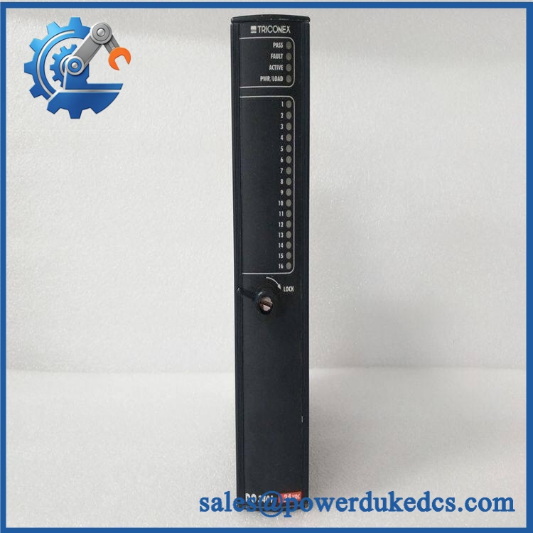
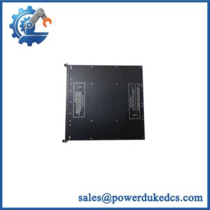
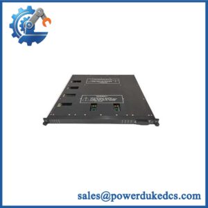
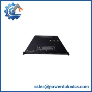
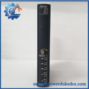
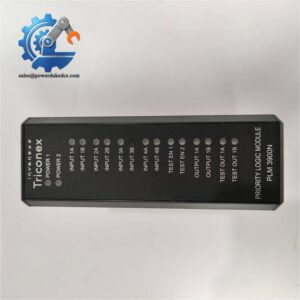
TRICONEX 3401
Module 5: Migration, Compatibility & Installation Traps
Replacement Matrix
| Replacement Type | Assessment |
|---|---|
| Drop-in Replacement | Conditional — suitable for an exact 3401 replacement in a compatible Trident I/O assembly |
| Software Compatible | Conditional — verify Trident controller revision, I/O configuration, application database, and output-channel assignments |
| Hardware Modification Required | Normally no for an exact 3401 replacement; baseplate, termination arrangement, field supply, and load characteristics must match |
⚠️ Field Traps — Watch Out
1. Do not confuse 3401 with 3401S2.
Current Triconex lifecycle records distinguish the original 3401 as a Trident 24 VDC 16-point TMR digital-output module, while 3401S2 is the corresponding Tri-GP assembly. They belong to different controller families and should not be treated as interchangeable.
2. Verify the field-load current, not just the nominal voltage.
The module’s switching capability is specified at 3 A typical, with self-limiting operation below 4.8 A. A load with excessive inrush or unsuitable protection can produce output faults even when the nominal coil voltage is 24 VDC.
3. Check the output loopback behavior during commissioning.
The documented thresholds distinguish Off, transition, and On states. A measured voltage in the 6–14 VDC transition region should not be interpreted as a healthy fully energized output. Investigate the load, wiring, and supply conditions.
4. Preserve the original channel mapping.
The 3401 contains 16 output points. During replacement, photograph the termination wiring and software channel assignments before removal. A healthy module with two swapped field conductors can still produce an incorrect safety action.
Module 6: Quality Assurance SOP
- OEM anti-counterfeit visual inspection — inspect TRICONEX identification, model 3401 marking, front-panel legends, channel indicators, locking mechanism, connectors, and visible manufacturing details.
- Exact part-number verification — confirm 3401 against the purchase order, physical label, and inventory record.
- Controller-family verification — confirm the intended installation is a Trident system rather than Tri-GP, where the corresponding module is 3401S2.
- Mechanical inspection — check the baseplate connector, keying features, ejector/locking hardware, housing, and PCB surfaces for bent contacts, contamination, corrosion, cracks, or impact damage.
- Power-on self-test (POST) — energize the module in an approved Trident test chassis and record PASS/FAULT/ACTIVE/PWR-LOAD indications, startup behavior, current draw, and abnormal temperature rise. The front-panel status indicators are documented in the Trident installation guide.
- Output simulation test — drive representative output channels into controlled test loads and verify correct ON/OFF switching at the specified 24 VDC supply conditions.
- 16-channel verification — test all 16 outputs independently where the laboratory fixture permits. Record commanded state, measured output voltage, load current, loopback status, and diagnostic result channel by channel.
- Current-limit verification — where the approved test fixture supports it safely, verify operation under controlled load conditions against the documented self-limiting output behavior. Do not create an uncontrolled short-circuit test.
- Loopback verification — measure representative output points and confirm the documented thresholds: 0–5 VDC Off, 6–14 VDC transition, and 15–30 VDC On.
- Fault simulation — use an approved diagnostic fixture to simulate permissible output faults such as field-power loss or short-circuit conditions and confirm the corresponding alarm/status response.
- TMR verification — where the laboratory setup permits, verify the three-channel I/O architecture and proper output behavior with compatible Trident processors and the appropriate digital-output baseplate.
- Hot-sparing verification where required — for applications using online maintenance, verify the approved hot-spare procedure and confirm that the replacement module is correctly recognized by the Trident system before release.
- Final QC and packaging — record part number, hardware revision, 16-channel test results, diagnostic status, photographs, ESD protection, and packaging condition before shipment.
Engineering note: The strongest technical evidence identifies TRICONEX 3401 as the Trident 16-point digital-output module, using 24 VDC nominal output, 15–30 VDC operating range, and a triplicated I/O architecture. The documented output stage supports 3 A typical switching current and provides field-voltage loopback diagnostics.



 Start Chat


