

Description
- Brand: TRICONEX
- Full Model Number: 3500 / 9753-110
- System/Series Family: Tricon v9–v10 Pulse Input / Pulse Totalizer I/O
- One-Sentence Core Function: Passive field termination panel for connecting compatible Tricon pulse-input or pulse-totalizer modules to field sensors
- Top 3 Hardcore Specs: 8 pulse-input points; 16 pulse-totalizer points; non-isolated field termination interface
- Stock Status: New Surplus / Factory Original — verify intended I/O module and panel configuration before shipment
Module 3: Technical Product Introduction
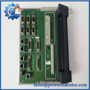
A pulse-input fault is easy to misdiagnose when the termination panel is treated as ordinary wiring hardware. The TRICONEX 9753-110 is a basic field termination panel used with compatible Tricon pulse-input and pulse-totalizer modules. Tricon technical documentation identifies it as supporting 8 points when paired with pulse-input modules and 16 points when paired with pulse-totalizer modules. The panel is passive; the signal-processing function resides in the associated Tricon I/O module.
The exact I/O pairing determines how the 9753-110 is wired. With an 8-point pulse-input module, the panel provides eight differential signal pairs, IN+ and IN−. With a 32-point pulse-totalizer module, two 9753-110 panels are required to expose all 32 points, giving 16 signal pairs per panel. Tricon’s technical guide lists 3510 and 3511 pulse-input modules and 3515 pulse-totalizer input as compatible applications.
Module 4: Application Scenarios & Field Realities
- For turbine-speed and rotating-equipment measurement, the 9753-110 provides the field termination interface for compatible Tricon pulse-input modules. The documentation shows typical connections for passive speed sensors, with separate IN+ and IN− wiring for each pulse channel.
- When a pulse channel appears dead while the I/O module passes diagnostics, inspect the sensor wiring, termination points, connector, and grounding arrangement before replacing the electronics. The 9753-110 sits directly in that physical signal path, so a loose or miswired termination can mimic an input-module fault.
- For pulse-totalizer applications, remember that the point count changes with the module type. The panel supports 16 input pairs per panel, while a compatible 32-point pulse-totalizer module requires two panels. Ordering one panel for a full 32-point installation leaves half the field interface unavailable.
- During brownfield cabinet replacement, keep the original field wiring map with the panel. The 9753-110 is a termination component rather than a programmable device, but incorrect conductor placement can still reverse IN+/IN− polarity or move a sensor onto the wrong channel.
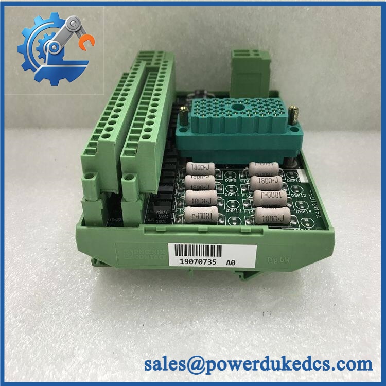
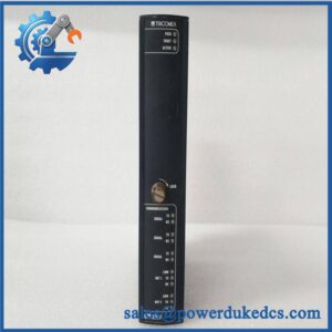
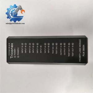
TRICONEX 3500 9753-110
Module 5: Migration, Compatibility & Installation Traps
Replacement Matrix
| Replacement Type | Assessment |
|---|---|
| Drop-in Replacement | Yes, when replacing an identical 9753-110 in the same compatible Tricon field-termination arrangement |
| Software Compatible | Not applicable — passive termination panel with no firmware or application logic |
| Hardware Modification Required | Normally no for an exact replacement; compatible I/O module, cable, sensor wiring, and termination topology must match |
⚠️ Field Traps — Watch Out
1. 9753-110 is not a universal Tricon termination panel.
The same model is documented in more than one Tricon application. For pulse input it supports 8 points; for pulse totalizer input it supports 16 points. A replacement must therefore be matched to the actual I/O module behind it.
2. Do not confuse the 9753-110 with a processing module.
The field termination panel contains the field connection hardware; signal detection and processing are performed by the associated pulse-input or pulse-totalizer module. The Tricon technical guide explicitly lists 3510, 3511, and 3515 as the relevant module families.
3. Preserve differential-pair wiring.
For pulse-input service, each channel uses IN+ and IN− connections. Reversing or misplacing these conductors can produce unstable or missing pulse detection even when the termination panel itself is electrically intact.
4. Pay attention to sensor grounding and shielding.
The documented field wiring calls for a quiet functional earth for shields where applicable. In high-speed pulse applications, poor grounding can create false counts or intermittent triggering that looks like an electronic module failure.
Module 6: Quality Assurance SOP
- OEM anti-counterfeit visual inspection — inspect TRICONEX identification, 9753-110 marking, panel labels, terminal blocks, connector hardware, mounting features, and visible manufacturing information.
- Exact part-number verification — confirm 9753-110 character-for-character against the purchase order and physical panel. Record 3500 only as the customer’s supplied system/reference designation unless the installed documentation confirms its specific meaning.
- Application verification — identify whether the panel is being used with a 3510/3511 pulse-input module or a 3515 pulse-totalizer module.
- Point-count verification — confirm the intended configuration: 8 pulse-input points or 16 pulse-totalizer points per panel. For a 32-point pulse-totalizer module, verify that two panels are present.
- Mechanical inspection — inspect terminals, connectors, mounting hardware, insulation, labels, and PCB-free passive components for cracks, corrosion, loose hardware, or contamination.
- Continuity verification — perform point-to-point continuity checks for every field terminal according to the approved pin map. Record each channel individually.
- Polarity and pair verification — verify every pulse-input pair as IN+ / IN− and confirm that channel numbering agrees with the cabinet wiring diagram.
- Shield and grounding inspection — verify field-shield termination and functional-earth connections against the approved Tricon wiring documentation.
- Installed signal-path verification — connect the panel to a compatible test I/O module and apply controlled pulse signals from an approved test source. Confirm that each intended channel is detected correctly.
- Communication handshake verification — not applicable as a standalone panel test. Communication should be verified at the complete Tricon I/O-system level after the termination panel is connected to the appropriate pulse-input module.
- Field simulation — for pulse-input applications, use a calibrated pulse generator to verify stable detection at representative frequencies. For pulse-totalizer applications, confirm correct counting with the complete module and test fixture.
- Final QC and packaging — record the exact panel number, application/module pairing, continuity results, inspection photographs, terminal condition, and protective packaging before shipment.
Engineering note: The supplied notation TRICONEX 3500/9753-110 should be handled carefully. The technically supported hardware identification is Tricon 9753-110, a basic field termination panel. Tricon documentation specifies 8 pulse-input points or 16 pulse-totalizer points per panel, with compatibility for 3510, 3511, and 3515 applications. Public technical evidence does not establish “3500” as a standalone model number for this termination panel, so it should not be presented as such without the original nameplate or BOM confirmation.



 Start Chat


