

Description
- Brand Triconex / Schneider Electric
- Full Model Number 3506X
- System/Series Family Tricon CX I/O Expansion Chassis
- Core Function TMR supervised digital input acquisition for 32 field points with optional end-of-line supervision
- Top 3 Hardcore Specs 32 input points | 0–28.8 VDC recommended range | <3 ms Off-to-On and On-to-Off input delay
- Stock Status New Surplus — verify hardware revision, Tricon CX chassis, termination panel, and supervision configuration before shipment
Module 3: Technical Product Introduction
A supervised input circuit is only useful when the controller can distinguish a legitimate field-state change from a wiring fault. Triconex 3506X is a TMR Supervised Digital Input Module designed specifically for the Tricon CX I/O expansion chassis. It provides 32 input points and can be configured as either supervised or non-supervised; supervised operation uses an end-of-line resistor network to monitor the field circuit. Schneider Electric’s Tricon CX documentation lists the module’s recommended input range as 0–28.8 VDC, with 32 VDC permitted only as the maximum over-voltage range.
The transition thresholds are deliberately defined for diagnostic use: 11.5 V Off-to-On, 7.5 V On-to-Off, with supervision high and low thresholds of 11.5–18.3 V and 5.5–7.5 V, respectively. Nominal turn-on current is 4.4–6.3 mA, input impedance is approximately 2.7 kΩ, and both switching directions are specified at less than 3 ms. The module also provides 1 ms SOE resolution and accuracy below 1 ms, with field-to-system-ground isolation rated at 400 Vrms continuous / 1500 VDC for 60 seconds.
Module 4: Application Scenarios & Field Realities
- In an emergency shutdown cabinet using Tricon CX, the 3506X can monitor field switches, valve-position contacts, shutdown permissives, and other discrete signals where supervision of the wiring itself is required. The TMR architecture processes the input independently across redundant channels before the data reaches the safety processors.
- For normally supervised field circuits, the optional end-of-line network becomes the important engineering detail. The documented resistor values are 1.69 kΩ series and 5.49 kΩ parallel, both with 1% tolerance. Those values should be installed at the field end according to the approved termination design; placing them at the cabinet can defeat the intended wiring-fault coverage.
- Where sequence-of-events data is important, the 3506X supports 1 ms SOE resolution and accuracy below 1 ms. The Tricon CX documentation also defines capture behavior for closely spaced events, including the ability to capture the first event on every point without loss under the documented conditions.
- During a maintenance replacement, remember that 3506X is a Tricon CX-only I/O module according to the referenced Schneider Electric guide. A card that matches the point count and voltage does not become a valid Tricon Classic replacement simply because the front-panel connector appears similar.
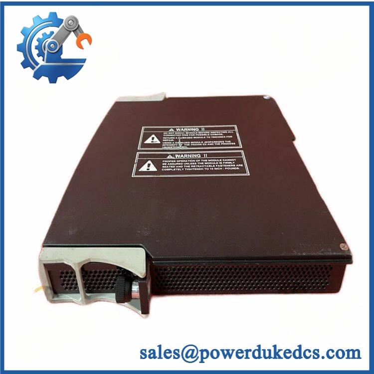
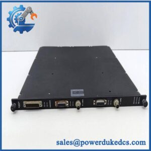
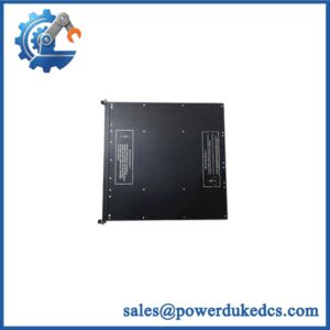
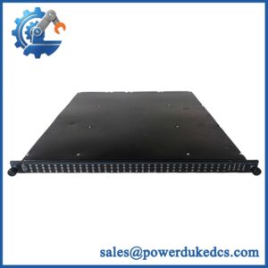
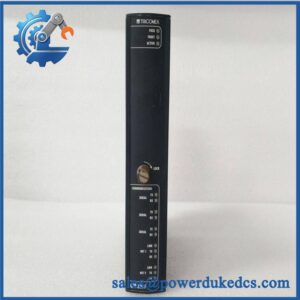
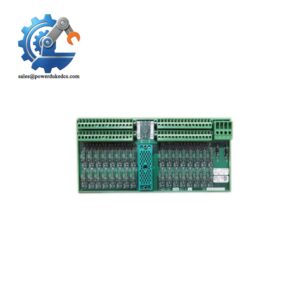
Triconex 3506X
Module 5: Migration, Compatibility & Installation Traps
Replacement Matrix
| Replacement Status | Engineering Assessment |
|---|---|
| Drop-in Replacement | Yes, only for a like-for-like 3506X installation in a compatible Tricon CX I/O expansion chassis using the correct termination hardware and approved configuration. |
| Software Compatible | Generally yes for an exact module replacement, but the TriStation configuration, supervision settings, point assignments, diagnostics, and approved Tricon CX firmware baseline must be checked. |
| Hardware Modification Required | Normally no for an exact 3506X replacement. Modification may be required when changing termination-panel type, supervised/non-supervised wiring, chassis generation, or field circuit architecture. |
⚠️ Field Traps: Watch Out
Do not apply the older Tricon 3503E specification to 3506X. The 3506X belongs to the Tricon CX platform and has a different supervised-input architecture. Schneider Electric explicitly states that 3506X can be installed only in Tricon CX I/O expansion chassis.
Do not exceed the documented usable input range. The Tricon CX guide identifies 0–28.8 VDC as the recommended range and 32 VDC as the maximum over-voltage range. A test source should be set from the exact controlled specification, not from a generic “24 VDC input” assumption.
Supervision resistors are part of the circuit design. For supervised points, the documented network uses 1.69 kΩ series and 5.49 kΩ parallel resistors. Changing either value can move the circuit into the wrong supervision band and create false field alarms or missed wiring faults.
Check the termination panel. The approved Tricon CX termination options include 9563X-910RF, 9566X-810RF, and 9570X-610RF, while 9770X is the associated field external termination connector. Individual field-power monitoring is not supported on the listed ETP configurations and must be disabled in TriStation where applicable.
Module 6: Quality Assurance SOP
A surplus 3506X should be tested as a supervised TMR input module in a Tricon CX-compatible laboratory setup. Every point should be exercised where the test fixture permits.
- OEM anti-counterfeit visual inspection: Verify Triconex/Schneider Electric identification, exact 3506X designation, dark-red module stripe, PCB revision, connector geometry, front-panel labeling, and manufacturing identifiers against controlled references.
- Part-number and traceability check: Record the complete model number, hardware revision, serial number, date code, and associated termination-panel/FET configuration.
- Mechanical inspection: Examine the backplane connector, housing, locking and keying features, PCB, front panel, and field interface for bent contacts, corrosion, contamination, cracking, or unauthorized rework.
- Power-on self-test (POST): Install the module in an approved Tricon CX test arrangement and verify expected Pass, Fault, Active, and Field status indications.
- Field-supply verification: Apply a controlled DC source within the verified operating envelope and monitor module behavior and power consumption.
- 32-channel functional test: Exercise all 32 input points individually and confirm correct On/Off status reporting.
- Threshold verification: Test representative transitions around the documented 11.5 V Off-to-On and 7.5 V On-to-Off thresholds, while avoiding operation outside the approved electrical range.
- Supervision test: For supervised points, install the specified end-of-line resistor network and verify the high and low supervision thresholds. Confirm that an open-circuit and the approved fault conditions generate the expected field diagnostic response.
- Resistor verification: Measure the installed end-of-line components and confirm 1.69 kΩ series and 5.49 kΩ parallel, each at the specified 1% tolerance where the supervised configuration requires them.
- Input-delay verification: Apply controlled On-to-Off and Off-to-On transitions and verify less than 3 ms response in each direction under the documented test conditions.
- Input-impedance check: Verify representative channels against the documented approximately 2.7 kΩ nominal input impedance.
- SOE verification: Generate controlled input transitions and verify 1 ms resolution and accuracy below 1 ms. For a full system acceptance test, verify the documented closely spaced-event capture behavior.
- Isolation verification: Test field-to-system-ground isolation using the approved laboratory procedure, with reference to the documented 400 Vrms continuous / 1500 VDC for 60 seconds rating.
- Diagnostic fault coverage test: Apply controlled signal changes and wiring-fault conditions permitted by the test procedure and verify the expected module and point diagnostics.
- Termination compatibility test: Confirm correct mechanical and electrical mating with the intended 9563X-910RF, 9566X-810RF, or 9570X-610RF termination option, or the specified 9770X FET arrangement.
- System recognition test: Verify correct module recognition, point addressing, diagnostics, and data exchange through the Tricon CX I/O bus.
- Communication handshake verification: Confirm successful 32-point data exchange between the I/O module and Tricon CX processing system. The 3506X is an I/O module rather than a standalone Ethernet or Modbus interface.
- Hot-maintenance verification: Where the approved system procedure supports replacement while energized, verify module recognition and recovery through the documented Tricon CX maintenance procedure. Do not perform live removal solely as a bench test.
- Extended-run test: Cycle representative supervised and non-supervised points while monitoring state stability, diagnostic alarms, supply behavior, and abnormal temperature rise.
- Final QC record: Document exact revision, test voltage, all 32 channel results, supervision resistor values, threshold measurements, timing results, SOE performance, isolation test, termination configuration, diagnostic behavior, extended-run observations, traceability, and packaging status.
Technical Identification Note: Schneider Electric’s Tricon CX documentation identifies Model 3506X as a TMR Supervised Digital Input Module that can be programmed for supervised or non-supervised operation and can be installed only in Tricon CX I/O expansion chassis. It provides 32 inputs, a 0–28.8 VDC recommended range, 11.5 V / 7.5 V switching thresholds, <3 ms input delays, 2.7 kΩ nominal input impedance, and 1 ms SOE capability. The same document specifies the compatible termination options and the end-of-line resistor values for supervised circuits.



 Start Chat


