

Description
- Brand Triconex / Invensys
- Full Model Number AI3351 / Model 3351
- System/Series Family Trident Safety Instrumented System
- Core Function TMR analog input acquisition for 32 commoned 4–20 mA process signals
- Top 3 Hardcore Specs 32 commoned inputs | 4–20 mA nominal / 2–22 mA operating | 12-bit resolution
- Stock Status New Surplus — verify hardware revision, baseplate, termination arrangement, and field configuration before shipment
Module 3: Technical Product Introduction
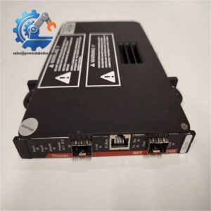
When a transmitter value becomes unstable, the fault may sit in the field loop, termination hardware, baseplate, or input electronics. Triconex AI3351 / Model 3351 is the Trident analog input module for 32 commoned 4–20 mA DC points. The module uses three independent electronic channels to process field data, sending the resulting values to the associated main processors, where the Trident architecture applies voting to the received information. It also supports continuous channel diagnostics and hot-sparing for online replacement.
The published electrical data is quite specific: nominal input current is 4–20 mA, with an operational range of 2–22 mA; maximum field voltage is 33 VDC, and maximum input current is 50 mA. Resolution is 12 bits, absolute error is specified at 0.15% of full scale at 20 mA, 3 dB input bandwidth is 16 Hz, and the module scans all 32 points in less than 1 ms. Functional-to-protective-earth isolation is at least 500 VDC, while functional-to-functional-earth isolation is at least 800 VDC.
Module 4: Application Scenarios & Field Realities
- On refinery pressure, flow, and level loops, AI3351 can acquire 4–20 mA transmitter signals while maintaining the Trident three-channel measurement architecture. For a failed reading, inject a calibrated current at the field termination before replacing the card; that quickly separates a transmitter/cable problem from an AI problem.
- Where dozens of continuous process variables terminate in one safety cabinet, the 32-point commoned arrangement provides high channel density. Channel mapping still deserves careful control. One crossed conductor can produce a completely believable process value on the wrong tag.
- In safety instrumented functions that depend on stable analog thresholds, the 12-bit conversion and sub-1 ms full-card scan time provide the measurement infrastructure, but the achieved safety performance depends on the complete loop, including transmitter diagnostics, logic configuration, proof testing, and final-element behavior.
- During an online maintenance event, the documented hot-spare capability allows a replacement module to be prepared while the active module remains in service. The exact procedure must follow the approved Trident maintenance method; do not treat hot sparing as permission to remove a module from an energized assembly without confirming the system state.
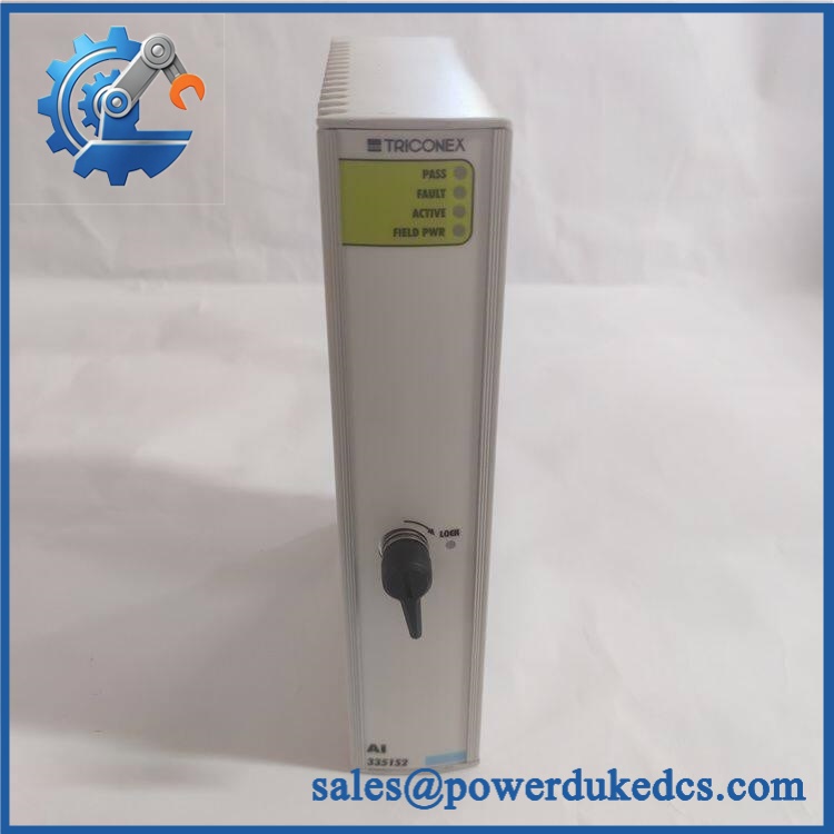
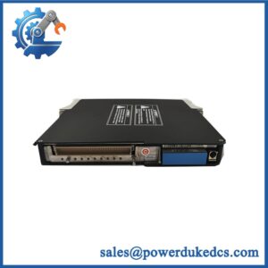
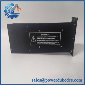
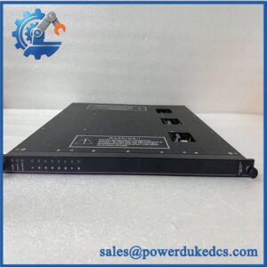
Triconex AI3351
Module 5: Migration, Compatibility & Installation Traps
Replacement Matrix
| Replacement Status | Engineering Assessment |
|---|---|
| Drop-in Replacement | Yes, for a like-for-like AI3351 / Model 3351 installation using the correct Trident baseplate and termination arrangement. |
| Software Compatible | Generally yes for an exact module replacement, but channel assignments, configured ranges, diagnostics, and the approved Trident application database must be verified. |
| Hardware Modification Required | Normally no for an exact AI3351 replacement. Hardware changes may be required when changing baseplate type, termination architecture, or migrating to a different Trident input module. |
⚠️ Field Traps: Watch Out
Do not confuse AI3351 with the baseplate. Trident documentation identifies 3351 as the Analog Input Module, while 2351 is the direct-termination analog-input baseplate and 2352 is the external-termination-panel baseplate. The module cannot be evaluated independently of the installed termination architecture.
Do not substitute from current-seller specifications without checking the original documentation. Some recent supplier pages advertise with 16-bit conversion, voltage inputs, thermocouples, RTDs, or other features that conflict with the Trident Model 3351 documentation. The controlled Trident specification identifies this module as a 32-point commoned 4–20 mA analog input module with 12-bit resolution.
Check loop resistance and input impedance. The documented input impedance with the baseplate is approximately 250 Ω, with a 180 Ω source impedance specification. Adding external devices, barriers, or unexpected series resistance can alter transmitter loop behavior.
Watch the 2–22 mA operating envelope. A normal transmitter should generally remain in the 4–20 mA range, but commissioning and fault diagnostics can produce values outside that band. Do not interpret every value below 4 mA as proof that the AI card is defective; investigate the transmitter and loop first.
Module 6: Quality Assurance SOP
A surplus should be tested point-by-point in a controlled Trident-compatible fixture. A successful module startup does not establish analog accuracy across all channels.
- OEM anti-counterfeit visual inspection: Verify Triconex/Invensys identification, / Model 3351 marking, PCB revision, connector geometry, front-panel indicators, and manufacturing identifiers against controlled references.
- Part-number and traceability check: Record exact module designation, hardware revision, serial number, date code, and associated baseplate/termination information.
- Mechanical inspection: Examine the backplane connector, enclosure, locking/keying mechanism, PCB, and field interface for bent contacts, corrosion, contamination, cracking, or unauthorized rework.
- Power-on self-test (POST): Install the module in an approved Trident test arrangement and verify expected initialization and front-panel PASS, FAULT, ACTIVE, and FIELD PWR behavior.
- 24 VDC field-supply verification: Apply the approved field supply through the correct 3351 baseplate and confirm stable operation without abnormal current draw.
- 32-channel analog test: Inject calibrated 4–20 mA signals into every channel and verify correct tag/channel association and measurement response.
- Operational-range test: Exercise representative channels at approximately 2 mA, 4 mA, 12 mA, 20 mA, and 22 mA to confirm behavior across the documented operating range.
- Resolution and accuracy verification: Compare measured values against calibrated standards and document results against the applicable 12-bit / 0.15% full-scale specification.
- Input impedance verification: Check representative channels against the documented approximately 250 Ω input impedance with the baseplate.
- Channel isolation verification: Confirm channel circuitry and grounding isolation using the approved test method; the specification calls for minimum 500 VDC functional-to-protective-earth isolation and 800 VDC functional-to-functional-earth isolation.
- Force-to-Value Diagnostic test: Execute the approved FVD sequence and verify the expected diagnostic response for representative channels.
- Scan-time verification: Where the laboratory fixture supports dynamic measurement, confirm full-card acquisition behavior consistent with the documented less-than-1-ms scan time for all 32 points.
- Hot-spare verification: Confirm the module can be recognized and made available as the configured spare in the approved Trident test environment.
- System recognition test: Verify correct module identification, channel addressing, diagnostics, and data transfer through the Trident I/O bus.
- Communication handshake verification: Confirm successful module-to-main-processor data exchange and correct three-channel data reporting. The AI module is not itself an Ethernet or Modbus interface.
- Extended-run test: Operate representative channels continuously while monitoring signal stability, diagnostic events, supply current, and abnormal temperature rise.
- Final QC record: Document hardware revision, all 32 channel results, calibration points, isolation results, FVD behavior, hot-spare recognition, system diagnostics, extended-run observations, traceability, and packing condition.
Technical Identification Note: Trident documentation identifies / Model 3351 as a 32-point commoned 4–20 mA analog input module using three independent processing channels. The controlled specification lists 2–22 mA operational range, 12-bit resolution, 0.15% full-scale absolute error, 16 Hz bandwidth, and less-than-1-ms scanning of all 32 points. Several current secondary listings publish materially different specifications, so the original Trident documentation should govern procurement and replacement decisions.



 Start Chat


