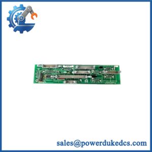
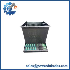
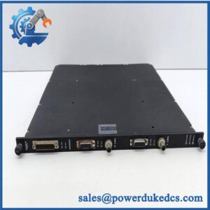
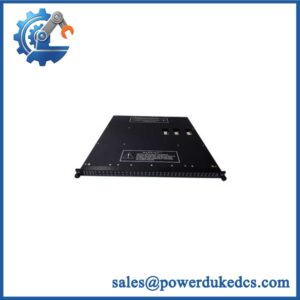
Description
-
Brand: TRICONEX
-
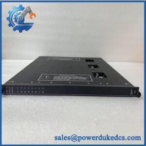
Full Model Number: AO3482, corresponding to Trident Model 3482
-
Product Type: High-Current Analog Output Module
-
System Platform: Triconex Trident safety and critical control system
-
Lifecycle Status: Legacy product; a published lifecycle overview lists Model 3482 as withdrawn from sale in April 2020. Current repair, support, and spare availability require confirmation.
-
Core Function: Triple Modular Redundant (TMR) analog output control for field devices
-
Top 3 Technical Specifications:
-
Output Channels: 4 commoned-return, DC-coupled points; points 1–2 support 4–20 mA, while points 3–4 support 4–40 mA
-
Resolution and Accuracy: 12-bit resolution; output accuracy below 0.25% of full-scale range under specified temperature conditions
-
Diagnostics: Forced-switch diagnostic (FSD); typical output-leg switching time of 1 ms, with a 3 ms maximum
-
-
Overrange Capability: 0–22 mA for points 1–2; 0–44 mA for points 3–4
-
External Loop Power: 24 VDC nominal; 32 VDC maximum, reverse-voltage protected
-
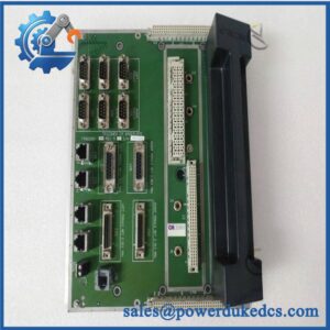
Required Baseplate: Trident Model 2481 Analog Output Baseplate
-
Stock and Condition: Physical inventory, serial identification, revision, and new or surplus condition subject to confirmation
-
Dispatch Lead Time: Confirmed against actual stock, inspection requirements, and carrier arrangements
-
Warranty: Written coverage and return conditions required before purchase order approval
Obsolescence and Supply Chain Deep Dive
A failed high-current analog output module can interrupt actuator commands and delay process restoration. The TRICONEX AO3482 serves Trident control systems that require current outputs above the standard 4–20 mA range on selected channels. Its four output points support two different current ranges, making accurate identification essential during replacement. The module also uses TMR architecture and forced-switch diagnostics to support fault detection and output control. For maintenance teams sourcing this legacy component, the main challenge is finding a unit with the correct hardware identity, output configuration, and mating baseplate. The AO3482 must be matched to the Trident Model 2481 Analog Output Baseplate and the installed field-wiring arrangement.
For an existing Trident installation, a verified AO3482 replacement may cost less than migrating the affected control system. Total Cost of Ownership (TCO) should include the module price, expedited freight, qualified labor, output-loop verification, commissioning, and downtime exposure. A like-for-like replacement limits immediate engineering work when the installed system remains suitable and the spare has the required output characteristics. Yet purchasing a legacy module does not eliminate future supply risks. Because the standard Model 3482 was listed as withdrawn from sale in a published lifecycle overview, procurement teams should confirm current support arrangements and establish a critical-spares plan. Where future availability remains uncertain, compare the cost of maintaining the installed system with a planned migration rather than waiting for another output failure.
Compatibility and Replacement Matrix
The AO3482 is a Trident high-current analog output module, not a general-purpose analog output card. Its channel ranges and baseplate requirements must match the original installation.
|
Replacement Scenario |
Compatibility Assessment |
Required Action |
|---|---|---|
|
Identical AO3482 with matching hardware identification |
Candidate drop-in replacement |
Verify the model designation, module condition, Model 2481 baseplate, and field connections |
|
Standard 3481 analog output module substituted for |
Not equivalent for all output requirements |
Check whether the application requires 4–40 mA outputs on points 3–4 |
|
installed with a different baseplate |
Compatibility not established |
Confirm the required Model 2481 baseplate and termination arrangement |
|
Replacement with a different hardware revision or assembly variant |
Requires engineering verification |
Compare the product identification, documented specifications, and installation requirements |
|
Replacement involving changes to current-loop wiring or field power |
Hardware modification may be required |
Review the circuit design, loop-power requirements, and approved wiring drawings |
|
Replacement requiring configuration or application changes |
Configuration verification required |
Confirm the controller application and output assignments before returning the system to service |
Replacement Cost and Time Estimates
The following figures are preliminary planning allowances, not manufacturer-approved service durations or supplier quotations.
|
Activity |
Preliminary Planning Allowance |
|---|---|
|
Part identification and compatibility review |
30–60 minutes |
|
Physical inspection and baseplate verification |
30–60 minutes |
|
Like-for-like replacement labor |
1–2 labor hours |
|
Output-loop and diagnostic testing |
1–3 labor hours |
|
Controlled functional verification |
1–2 labor hours |
|
Replacement module and expedited freight |
Supplier quotation required |
|
Preliminary maintenance window |
Approximately 2–5 hours, subject to site conditions |
These estimates assume that the replacement is available, the existing wiring documentation is accurate, and no engineering changes are required. Shutdown authorization, access restrictions, failed field devices, and additional functional-safety testing may extend the maintenance window.
Field Traps to Check Before Ordering
Different current ranges across output points: Points 1–2 operate in the 4–20 mA range, with 0–22 mA overrange capability. Points 3–4 operate in the 4–40 mA range, with 0–44 mA overrange capability. Verify each assigned field device against the correct output point before installation.
Shared return and baseplate configuration: The module uses four commoned-return, DC-coupled outputs. Do not assume independent point-to-point isolation. Confirm the Model 2481 baseplate, terminal assignments, field-power arrangement, and grounding requirements against the installed system.
Loop-power and load requirements: The external loop supply is rated at 24 VDC nominal and 32 VDC maximum. The permissible load depends on the output channel group and available loop voltage. For points 3–4, the documented load requirements differ from those for points 1–2. Check the load resistance, voltage drop, and field-power capacity before approving the replacement.
Safety-system maintenance: Do not assume that the module can be removed while energized. Follow the applicable Trident installation instructions and site-approved procedures for isolation, module replacement, and functional validation.
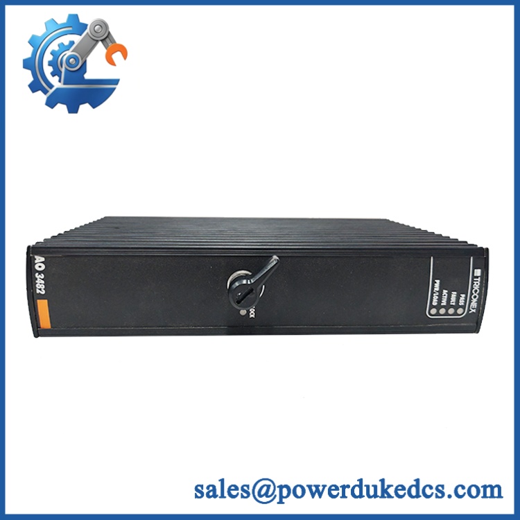
Triconex AO3482
Quality Assurance and Testing SOP
Pre-shipment QA for the TRICONEX should establish the unit’s identity, physical condition, and output performance. Testing must account for its TMR design, distinct channel ranges, and required baseplate.
|
QA Stage |
Required Procedure |
Acceptance Criteria |
|---|---|---|
|
Part identification |
Record the or Model 3482 designation, serial number where available, and identification markings |
Label information matches the purchase specification |
|
OEM anti-counterfeit visual inspection |
Examine labels, PCB markings where accessible, component condition, soldering, connectors, and evidence of unauthorized repair |
No unexplained identity discrepancies or physical defects affecting use |
|
Mechanical inspection |
Inspect the module housing, contacts, mounting features, and baseplate interface |
No damage, corrosion, or connector defects affecting installation |
|
Baseplate verification |
Confirm the required Model 2481 Analog Output Baseplate and the intended test arrangement |
Correct baseplate and termination configuration established |
|
Power-on self-test (POST) |
Power the module through an approved Trident test setup and record startup behavior |
Startup sequence agrees with the applicable technical documentation |
|
Status indicator verification |
Check the fitted PASS, FAULT, ACTIVE, PWR/LOAD, and LOCK indicators against the applicable operating instructions |
Indicator states recorded; any fault indication investigated |
|
TMR diagnostic testing |
Verify applicable diagnostic behavior using the approved test procedure |
Diagnostic responses meet the defined test criteria |
|
Output testing for points 1–2 |
Apply controlled test commands and measure current across the 4–20 mA operating range |
Output response meets the applicable acceptance limits |
|
High-current output testing for points 3–4 |
Exercise each channel across the documented 4–40 mA operating range using a suitable load |
Output response meets the applicable acceptance limits |
|
Loop-load verification |
Test the output with an appropriate controlled load and documented loop supply |
Current delivery is consistent with the specified load and voltage requirements |
|
Output fault diagnostics |
Test forced-switch diagnostic behavior where supported by the approved test procedure |
Diagnostic results recorded against the applicable criteria |
|
Final inspection and packing |
Photograph the actual module, record the completed tests, and use ESD-protective packaging |
Shipped unit matches the inspected item and its test documentation |
Pre-Shipment Test Report
The test report should identify the module, inspection date, test setup, loop-supply voltage, output loads, measured current values, and diagnostic results. Any untested function must be listed explicitly.
A power-on test alone does not verify analog output accuracy. Similarly, successful operation at 4–20 mA does not establish correct performance at 4–40 mA. Testing should cover both channel groups when the agreed service scope requires full functional verification.
Where a complete Trident test rack is unavailable, document the limitation before shipment. Do not describe untested channels or diagnostic functions as fully verified. Extended monitored testing should be claimed only when supported by recorded results.
Procurement and Lifecycle FAQ
Is the TRICONEX genuinely in stock, and what is the emergency shipping cutoff?
Physical availability must be confirmed for the exact module offered. Request written confirmation of quantity, product identification, condition, test coverage, and expected dispatch date. Emergency shipping depends on order approval, payment clearance, inspection, packaging, export documentation, and carrier collection. No fixed dispatch cutoff should be assumed without confirmation.
How do you verify the condition and authenticity of a surplus ?
Request photographs of the actual module, front-panel indicators, identification labels, connectors, and accessible PCB markings. The quotation should distinguish new original, new surplus, and used equipment, as applicable. Ask for available traceability records and a unit-specific inspection report. Visual inspection alone does not establish authenticity or complete functional performance.
Are there hardware compatibility issues to resolve before issuing the purchase order?
Yes. Confirm the required Model 2481 baseplate, output channel assignments, current ranges, common-return wiring, and field-loop power arrangement. Check whether the application requires 4–40 mA outputs on points 3–4. A matching module designation does not establish compatibility with every field circuit.
What warranty and return terms apply to the TRICONEX ?
The written quotation should specify the warranty period, coverage, defective-on-arrival procedure, return authorization requirements, and exclusions. For surplus or used modules, confirm whether coverage includes functional failure and which test records are required for a claim. Retain the identification photographs, inspection report, measured output results, and shipping documents.
Is replacing the more economical than migrating the Trident control system?
A verified replacement may have a lower immediate cost when the installed Trident system remains suitable and the required module and baseplate are available. Compare the module price, expedited freight, qualified labor, output-loop testing, and downtime exposure against the engineering, hardware, software, installation, and validation costs of a migration. Given the legacy lifecycle status, include future spare availability and the cost of a planned migration in the maintenance budget.