Description
- Brand: TRICONEX
- Model: DI2301
- Part Number Provided: 7400208-020
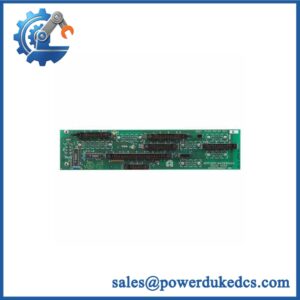
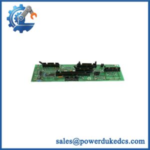
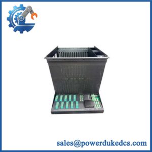
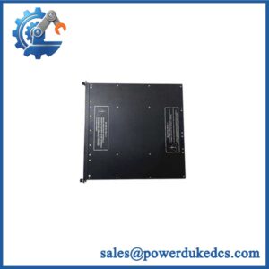
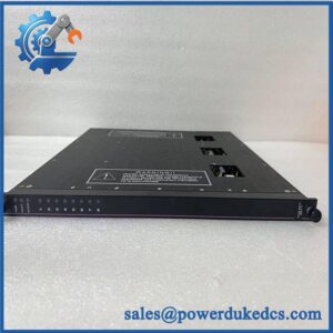
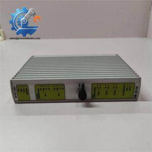
- Product Type: Digital input baseplate / field termination assembly
- System Family: Triconex Trident Safety Instrumented System
- Lifecycle Status: Legacy spare part; current OEM availability and support status require confirmation
- Core Function: Provides the physical mounting and electrical interface for digital input hardware and associated field wiring
- Input Configuration: Associated with 24 VDC digital input applications; verify the approved input module and field termination arrangement
- Assembly Identification: The Trident 2301 digital input baseplate kit is documented as comprising an I/O baseplate, interconnect assembly, slot cover, and terminal cover
- Part Number Verification: Confirm whether the required identifier is 7400208-020, 7400208B-020, or another revision-specific variant
- Stock & Condition: Quantity, exact part reference, physical condition, revision, testing records, and dispatch date require confirmation
Obsolescence & Supply Chain Deep Dive
A failed digital input baseplate can delay restoration of a safety instrumented system when the replacement must match an existing chassis, I/O module, and field wiring arrangement. The TRICONEX DI2301 is associated with the Trident digital input baseplate family. Its role is to provide the mounting and electrical interface for the relevant digital input hardware rather than act as a standalone safety controller. This distinction matters during procurement: a baseplate and an active input module are not interchangeable purchasing items. Confirm the installed assembly, associated module, terminal arrangement, and complete identification number before ordering. The supplied reference, 7400208-020, requires particular attention because related listings also use suffix variants.
Replacing the correct baseplate may preserve existing cabinet wiring and avoid the cost of modifying a larger section of the safety system. The total cost of ownership (TCO) calculation should include the spare assembly, maintenance labor, wiring verification, inspection, functional testing, and potential process downtime. For preliminary planning, allow approximately 2–4 maintenance labor hours for a straightforward replacement and initial checks, excluding extensive fault diagnosis and formal recommissioning. This is a planning estimate, not an OEM installation time. Before approving the purchase, obtain photographs of the actual assembly, verify its exact part number, and establish whether the supplied item includes all components required by the installation. In a safety instrumented system, an apparently similar baseplate must not be accepted as equivalent without engineering approval.
Compatibility & Replacement Matrix
| Replacement Scenario | Classification | Required Action | Preliminary Time Allowance |
|---|---|---|---|
| Exact DI2301 assembly with matching part number and revision | Conditional drop-in replacement | Verify chassis compatibility, interconnect assembly, terminal layout, and field wiring before installation. | 2–4 maintenance labor hours |
| DI2301 with a different part-number suffix or revision | Engineering verification required | Compare identification labels, mechanical interfaces, terminal arrangement, and applicable system documentation. | 2–4 engineering hours for initial review |
| Different digital input baseplate proposed as a substitute | Not an automatic replacement | Verify the matching input module, mounting arrangement, interconnect requirements, and validated system configuration. | Estimate after technical review |
| Alternative assembly requiring wiring or cabinet changes | Hardware modification may be required | Review electrical drawings, field termination, cable routing, and safety-system change-control requirements. | Site-specific estimate required |
Cost planning: The installed replacement cost consists of the assembly purchase price, maintenance labor, engineering review, required testing, and any outage-related expenses. Additional hardware or wiring changes may increase the cost. Obtain a quotation for the complete required assembly rather than pricing a component whose inclusion in the supplied kit has not been confirmed.
Field Traps to Check Before Ordering
- Part-number suffix mismatch: Verify the complete number on the installed baseplate. Related product listings use 7400208B-020 and other suffix variants. Do not assume these identifiers refer to identical hardware without documentation.
- Baseplate versus input module: Confirm whether the purchase specification calls for the DI2301 baseplate assembly, an active digital input module, or a complete kit. These items perform different functions.
- Interconnect compatibility: Check the chassis interface, interconnect assembly, slot position, and terminal arrangement against the installed configuration.
- Field wiring errors: Record conductor positions and verify signal identification before disconnecting the existing assembly. Do not rely solely on wire color or terminal position.
- Safety-system change control: Confirm the approved maintenance procedure, required bypass controls, impact on input availability, and applicable proof-test requirements. Do not assume the baseplate can be removed online.
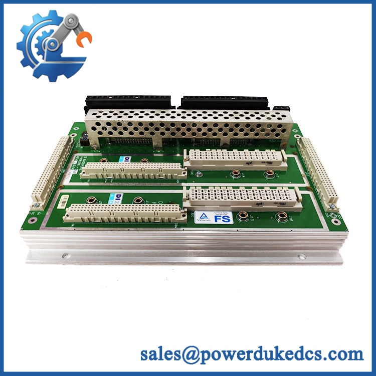
TRICONEX DI2301 7400208-020
Quality Assurance & Testing SOP
The following procedure defines a proposed inspection and acceptance scope for the TRICONEX DI2301. Testing must follow the approved Triconex documentation for the exact assembly and its associated digital input module.
Visual Inspection and Traceability
- Part-number verification: Compare the model designation and complete part number against the purchase order and installed hardware records.
- Assembly verification: Confirm which baseplate components are included, including any required interconnect, slot cover, and terminal cover.
- Physical inspection: Examine the baseplate, connectors, mounting points, terminal interfaces, and accessible surfaces for corrosion, impact damage, contamination, or unauthorized modification.
- Authenticity screening: Inspect manufacturer markings, label consistency, available serial or production details, and traceability records.
- Condition documentation: Record whether the unit is new original, new surplus, or previously used, as applicable.
- Photographic evidence: Capture the actual assembly, complete identification label, connectors, and included components before packaging.
Mechanical and Interface Checks
- Verify the baseplate dimensions, mounting arrangement, and chassis interface against the applicable assembly documentation.
- Inspect connectors and interconnect components for bent contacts, damaged locking features, or contamination.
- Confirm that the supplied components match the requested kit configuration.
- Check that the assembly fits the approved hardware arrangement without forcing connectors or modifying mounting points.
- Record any differences between the replacement and the installed unit.
Electrical and Functional Verification
- Perform electrical checks only with suitable test equipment and an approved test procedure.
- Verify continuity and applicable connections in accordance with the assembly drawings.
- Where testing the complete input circuit, use the correct associated digital input module and an approved test fixture.
- Apply controlled 24 VDC input signals only where supported by the documented hardware configuration.
- Verify that representative field input states are recognized correctly by the compatible test system.
- Record any relevant diagnostic indications and identify tests that could not be completed.
A passive baseplate should not be described as independently tested for digital input processing when no active input module is included. Functional test results must identify the actual equipment tested and the scope of the test.
Final Acceptance and Shipment Release
- Reconcile the actual part number and revision against the purchase order.
- Confirm that all specified assembly components are included.
- Provide actual-unit photographs and agreed inspection records.
- Document the test method, results, and any unperformed checks.
- Package the assembly with suitable electrostatic-discharge protection where applicable and adequate mechanical protection.
- Release the unit only after the agreed acceptance requirements have been met.
Testing limitation: A baseplate inspection does not establish the safety integrity or correct operation of the complete Trident system. Following installation, qualified personnel must verify field wiring, module recognition, relevant input states, diagnostics, and required safety-function tests under the approved site procedure.
Procurement & Lifecycle FAQ
Is the TRICONEX 7400208-020 in stock, and what is the emergency shipping cutoff?
Availability must be confirmed against the physical inventory for the exact part number and revision. Request the available quantity, condition, included components, warehouse location, and confirmed dispatch date. Emergency shipping depends on payment clearance, export documentation, packaging, and carrier collection times. Same-day dispatch requires written confirmation.
How do you verify the authenticity and condition of this discontinued assembly?
Request photographs of the actual baseplate, complete identification label, connectors, and included accessories. Ask for available traceability records and a written condition declaration. If electrical or functional testing is required, define the scope before ordering. Inspection of a passive baseplate alone does not establish the functional performance of the associated input module.
Will the work with my existing Triconex system?
Compatibility depends on the installed Trident hardware, baseplate revision, interconnect assembly, associated input module, and field termination arrangement. Confirm the complete part number and compare the assembly against the existing installation documentation. Engineering approval is required before accepting a different revision or substitute.
What warranty and return terms should be confirmed before purchasing?
Confirm the warranty period, commencement date, defect coverage, exclusions, return authorization procedure, and deadline for reporting a defective-on-arrival unit. Establish who pays return freight and what inspection evidence is required to process a claim. Put the agreed terms in the quotation or purchase order, particularly for surplus inventory.
Can a different Triconex digital input baseplate replace the ?
Not automatically. A substitute must match the required chassis interface, interconnect arrangement, associated input module, and approved field wiring configuration. Verify whether the proposed item is a complete baseplate kit or an individual component. Any substitution in a safety instrumented system must follow the site’s engineering approval and change-control procedures.