

Description
- Brand: TRICONEX
- Full Model Number: DI3301S2 / 3301S2
- System/Series Family: Triconex General Purpose v2 / Tri-GP safety control system
- Core Function: 32-channel commoned 24 VDC digital input acquisition with internal diagnostics
- Top 3 Hardcore Specs: 32 points; 24 VDC nominal; 19.2–30 VDC operating range
- Stock Status: Verify current New Surplus, Factory Sealed, or Fully Tested Refurbished condition before order
Module 3: Technical Product Introduction
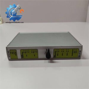
A digital-input failure can remove a large group of field permissives, alarms, status contacts, or shutdown indications from a controller at once. The TRICONEX DI3301S2, also designated Model 3301S2, is a 32-point digital input module for the Tri-GP v2 platform. The Triconex planning guide specifies 32 commoned inputs, a 24 VDC nominal input, and an operational range of 19.2 to 30 VDC. Its architecture connects the input circuitry to the controller through triplicated I/O bus interfaces with isolated bus transceivers.
The input thresholds are deliberately defined for a 24 VDC control circuit: 0–5 VDC is the OFF region, 6–14 VDC is the transition region, and 15–30 VDC is the ON region. Input delay is specified by a time constant of 2.86 ms, with a -3 dB point at 55 Hz, while input impedance is greater than 30 kΩ without the baseplate and approximately 3 kΩ with the baseplate. The module also uses a force-to-value diagnostic, with the published diagnostic response specified at less than 2 ms per test.
Module 4: Application Scenarios & Field Realities
- Inside a Tri-GP control cabinet, DI3301S2 is suited to dense acquisition of 24 VDC discrete signals such as motor-running contacts, valve-position switches, permissives, alarm contacts, and interlock indications. With 32 commoned points, the module is intended for applications where multiple field devices share the same input reference.
- During brownfield replacement, the 19.2–30 VDC operating range should be checked against the actual field supply rather than the nominal 24 V label alone. A supply drifting near the input threshold can create intermittent state transitions that look like a software problem.
- Where the cabinet uses a hot-spare strategy, the Tri-GP technical guide states that DI modules support a hot-spare module and are mechanically keyed to prevent installation in an incompatible configured baseplate. That makes the baseplate part number an important procurement check, not just the DI module number.
- When signal response time matters, DI3301S2 should not be confused with the higher-resolution 3311S2 module. Both provide 32 commoned inputs, but 3311S2 has a much faster specified input response, while 3301S2 uses the 2.86 ms time constant.
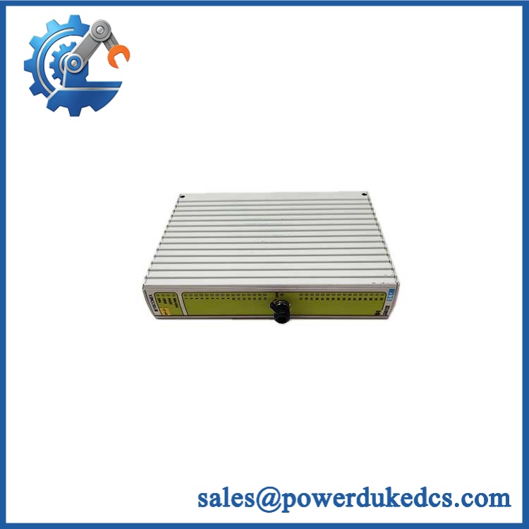
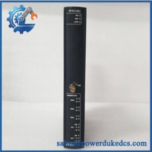
TRICONEX DI3301S2
Module 5: Migration, Compatibility & Installation Traps
Replacement Matrix
Exact DI3301S2 / 3301S2 configuration: Drop-in Replacement
For an existing Tri-GP installation using the same DI module, approved baseplate, field termination arrangement, and controller configuration, the replacement is normally a direct hardware exchange.
3311S2 substituted for 3301S2: Software Compatible / Hardware Verification Required
Both are 32-point, 24 VDC digital-input modules, but the input timing characteristics differ substantially. The 3311S2 is the high-resolution variant and should not be substituted solely because the channel count and nominal voltage match.
3301S2 with a different baseplate or termination assembly: Hardware Modification Required unless approved
The technical guide identifies the 2301S2 baseplate for typical applications, while other baseplate arrangements are used for special external termination and hazardous-location installations. Confirm the complete I/O assembly before procurement.
⚠️ Field Traps (Watch Out)
Threshold-region trap: HIMA? No. For Triconex DI3301S2, 6–14 VDC is a transition region, not a clean logic state. A weak field supply, excessive contact resistance, or long wiring run can place the input in this region and produce unstable diagnostics. The specified ON region begins at 15 VDC.
Commoned-input trap: All 32 points are specified as commoned. Do not assume each channel has independent galvanic isolation. Review the field wiring and common reference arrangement before using the card in a cabinet designed around individually isolated inputs.
Revision confusion: Public inventory records identify as a discontinued Triconex VDC logic I/O module, while technical documents identify the underlying 3301S2 hardware and specifications. Retain the complete ordering designation from the physical label when creating a spare-parts record.
Module 6: Quality Assurance SOP
Pre-Shipment QA Protocol for TRICONEX
- Step 1 — Identity Verification: Confirm TRICONEX marking, / 3301S2 designation, serial number, hardware revision, manufacturing information, and any associated baseplate identification.
- Step 2 — OEM Anti-Counterfeit Visual Inspection: Examine labels, barcodes, PCB markings, connector bodies, keying features, fasteners, front-panel legends, and evidence of unauthorized modification.
- Step 3 — Mechanical Inspection: Inspect the module housing, card edge, mating connector, locking hardware, alignment keys, and enclosure for damage, corrosion, contamination, or deformation.
- Step 4 — Input Fixture Verification: Prepare a controlled 24 VDC digital-input test source and verify that the test fixture is referenced correctly for the commoned-input architecture.
- Step 5 — Power-On Self-Test: Install the module in an approved Tri-GP test configuration and verify normal startup, controller recognition, module diagnostics, and status indications.
- Step 6 — 32-Channel Input Test: Exercise all 32 channels individually through OFF, transition, and ON conditions. Verify correct recognition against the documented 0–5 V, 6–14 V, and 15–30 V regions.
- Step 7 — Input Timing Test: Apply controlled signal transitions and verify response behavior against the documented 2.86 ms time constant.
- Step 8 — Diagnostic Verification: Execute the approved force-to-value diagnostic test and confirm the module reports expected diagnostic responses without unexplained channel faults.
- Step 9 — Stability Test: Operate representative channels through repeated state changes while monitoring for false transitions, intermittent inputs, abnormal heating, or controller communication faults.
- Step 10 — Final QC Record: Record complete model identification, revision information, all 32 channel results, timing-test result, diagnostic status, measured supply voltage, visual condition, test date, and final QC disposition.
Technical Verification Note: The Triconex Tri-GP technical documentation identifies 3301S2 as a 32-point, commoned digital input module with 24 VDC nominal input, 19.2–30 VDC operating range, 33 VDC absolute maximum input, 0–5 VDC OFF, 6–14 VDC transition, and 15–30 VDC ON thresholds. The specified input timing is a 2.86 ms time constant, and the module supports force-to-value diagnostics.



 Start Chat


