

Description
- Brand: Woodward
- Full Model Number: BUM60-1224-54-B-001-VC-A0-0093-0013-G003-0000 / 3522-1004
- Lifecycle Status: Legacy / Replacement Available
- Core Function: EM-80 / EM-300 electric actuator driver
- Top 3 Technical Specs: 400–480 VAC three-phase motor supply; 24 VDC control supply; closed-loop resolver feedback
- Actuator Compatibility: EM-80 / EM-300
- Motor Type: Three-phase brushless AC motor
- Control: Position / current / torque control
- Feedback: Resolver
- Installation: Control cabinet
- System: Woodward EM-80 / EM-300 All-Electric Actuator System
- Stock & Condition: New Surplus / Tested Refurbished — physical stock confirmation required
Woodward documentation identifies the 3522-1004 through 3522-1012 range as EM-80/EM-300 actuator drivers. The system uses a dedicated driver, actuator, resolver cable, motor cable, and associated power/EMI equipment.
Module 3: Obsolescence & Supply Chain Deep Dive
A failed 3522-1004 can take an electrically actuated fuel valve or other prime-mover positioning function out of service even when the upstream turbine or engine controller remains operational. The key point for procurement is identification: 3522-1004 is the EM-80/EM-300 driver, while the BUM60 designation refers to the associated actuator system configuration seen in this ordering string. The driver converts three-phase 400–480 VAC, 50–60 Hz input into controlled motor power and uses a separate 24 VDC supply for its internal electronics. Resolver feedback closes the actuator-position loop.
For an installed EM-80/EM-300 system, a verified 3522-1004 replacement can avoid changing the actuator, linkage, control philosophy, and field installation. Woodward’s later EM-80/EM-300 documentation explicitly discusses replacing earlier driver models such as 3522-1004, 3522-1005, and 3522-1009 with newer 3522-1042 hardware, with a dedicated retrofit procedure rather than assuming direct interchangeability. That creates a strong TCO case for maintaining a tested legacy spare where the existing driver architecture remains approved. —The procurement decision should be based on the exact driver part number, actuator type, revision, wiring, and retrofit status rather than the BUM60 label alone.
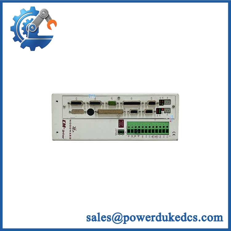
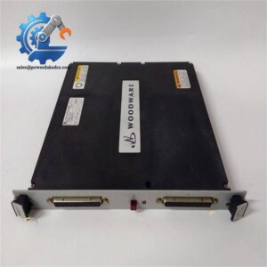
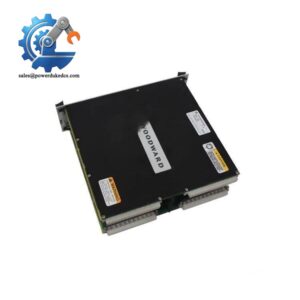
Woodward 3522-1004
Module 4: Compatibility & Replacement Matrix
| Approval Question | Assessment for 3522-1004 / BUM60 Configuration |
|---|---|
| Product Type | EM-80 / EM-300 electric actuator driver |
| Replacement Type | Drop-in replacement only for a matching 3522-1004 installation |
| Actuator Compatibility | EM-80 / EM-300 system |
| Motor Supply | 400–480 VAC, three-phase, 50–60 Hz |
| Control Supply | 24 VDC |
| Feedback | Resolver position feedback |
| Installation | Control cabinet |
| Software | Configuration/setup software required as applicable |
| Firmware | Revision-dependent; verify driver configuration before replacement |
| Hardware Modification | Normally none for exact like-for-like replacement |
| Typical Field Swap | 4–8 hours, including wiring checks and actuator commissioning |
| Engineering Effort | Low for identical spare; medium/high for migration to later driver |
Woodward’s actuator documentation confirms that the EM-80 and EM-300 use the same basic motor/driver concept, with the driver controlling actuator position and receiving resolver feedback. The EM-80 uses a 1:7 gearbox, while the EM-300 uses a 1:20 gearbox, so actuator identification remains important.
Field Traps — Watch Out
- Legacy-driver replacement: Woodward specifically identifies 3522-1004 as an earlier EM-80/EM-300 driver and provides a retrofit path to newer hardware such as 3522-1042. Do not approve a newer driver as a simple plug-for-plug substitute without following the conversion documentation.
- EM-80 versus EM-300 configuration: The two actuators share the dedicated driver but have different gearbox ratios and, for EM-300, an additional 10-turn potentiometer for coarse position information. Verify actuator type before commissioning.
- Resolver wiring: Woodward specifies a dedicated resolver cable, and the position-feedback signal is essential to closed-loop actuator operation. Incorrect shielding, connector termination, or cable routing can produce position faults even when the driver powers up normally.
- 24 VDC supply: The motor power circuit and internal control supply are separate. Confirm the protected 24 VDC supply before troubleshooting a driver that appears to have no control response.
Module 5: Quality Assurance & Testing SOP
Because the 3522-1004 switches high-power three-phase motor energy and performs closed-loop actuator control, testing should be performed using a controlled industrial test fixture by qualified personnel.
1. Identity & Authenticity Verification
- Verify Woodward branding and exact 3522-1004 part number.
- Cross-check the complete BUM60 ordering string against the procurement specification.
- Record serial number, manufacturing information, hardware revision, and visible software/firmware information.
- Perform OEM anti-counterfeit visual inspection of enclosure, labels, connectors, terminal blocks, cooling components, and PCB markings.
2. Physical Inspection
- Inspect power terminals for overheating, discoloration, looseness, or arcing evidence.
- Check control and feedback connectors.
- Inspect the enclosure for cracks, contamination, corrosion, or unauthorized repair.
- Verify mounting hardware and cabinet interfaces.
- Confirm no foreign material is present in cooling paths.
3. Electrical Safety Tests
- Verify protective-earth continuity.
- Perform appropriate insulation-resistance testing under the approved laboratory procedure.
- Check the 24 VDC control supply input circuit.
- Verify the three-phase power input circuitry before energization.
- Confirm there are no abnormal shorts between power, control, and feedback circuits.
4. Power-On Self-Test
- Install the driver in a controlled test cabinet.
- Apply the specified 24 VDC control supply.
- Apply three-phase AC only after the preliminary electrical checks pass.
- Perform the driver’s startup diagnostics.
- Check front-panel status and fault indications.
- Record any overvoltage, undervoltage, overtemperature, motor, or feedback alarms.
5. Motor & Actuator Functional Test
- Connect the correct EM-80 or EM-300 actuator test arrangement.
- Verify resolver feedback.
- Apply controlled position commands.
- Confirm actuator movement in both directions.
- Verify position tracking and stopping behavior.
- Check current and torque response under representative load.
- Confirm travel limits and configured operating range.
6. Feedback & Fault Testing
- Introduce controlled resolver-feedback fault conditions.
- Verify appropriate diagnostic response.
- Check loss-of-feedback behavior.
- Verify emergency-stop or minimum-position response where the test arrangement supports it.
- Confirm Ready-for-Use and common-alarm indications.
Woodward’s documentation describes an isolated pulse-enable input that controls the driver’s power stage, a reset input for alarms, and Ready-for-Use/common-alarm outputs. These functions should be incorporated into a complete acceptance test where applicable.
7. Extended Stability Test
- Run representative actuator positioning cycles.
- Monitor motor current, DC supply stability, driver temperature, resolver feedback, and diagnostic status.
- Repeat position commands after thermal stabilization.
- Record any unexpected trips, resets, feedback deviations, or overtemperature events.
8. Final QC Release
- Match the tested serial number with the sales documentation.
- Record tested actuator type: EM-80 or EM-300.
- Record hardware and software/firmware revisions.
- Issue a serial-number-specific QC/Test Report.
- Package the driver with ESD protection and mechanical protection around the connectors and terminals.
Module 6: Procurement & Lifecycle FAQ
Q1. Is Woodward 3522-1004 genuinely in stock, and what is the emergency-shipping cutoff?
Physical inventory should be confirmed against the exact 3522-1004 designation, serial number, condition, and hardware revision. Current supplier records show active stock listings, but actual quantity and condition must be verified before PO release. For an emergency turbine or engine repair, require written confirmation of dispatch date and same-day carrier cutoff.
Q2. How do you verify the condition and authenticity of a surplus 3522-1004?
Require exact part-number verification, serial-number recording, OEM marking inspection, power-stage inspection, controlled 24 VDC startup, three-phase electrical testing, resolver-feedback verification, actuator positioning, fault-response testing, and an extended stability run. A cosmetic inspection alone is not adequate for this class of actuator driver.
Q3. Are there firmware or configuration compatibility issues I should warn my engineers about?
Yes. The driver is configurable for the EM-80/EM-300 actuator system, and the specific application wiring and configuration must be verified. Woodward’s newer documentation also identifies a formal retrofit process when earlier drivers such as 3522-1004 are replaced by later models.
Q4. Can 3522-1004 directly replace another Woodward EM driver?
Do not assume cross-replacement solely from the EM-80/EM-300 name. Woodward documents multiple driver part numbers and a specific retrofit process. The replacement decision should consider the existing actuator, driver revision, resolver arrangement, control wiring, software configuration, and retrofit instructions.
Q5. What warranty and return protection should apply to a surplus 3522-1004?
The quotation should specify the exact part number, physical condition, hardware revision, warranty period, functional-failure coverage, return procedure, and pre-shipment test scope. For a critical actuator driver, require the Test Report to identify the actual serial-numbered unit and document both power-stage and closed-loop actuator testing.



 Start Chat


