

Description
- Brand: Woodward
- Full Model Number: 3522-1005
- Lifecycle Status: Legacy / Replaced
- Core Function: EM-80 electric actuator driver, clockwise rotation configuration
- Top 3 Technical Specs: 24 VDC nominal control supply; 3-phase AC motor drive; EM-80 actuator compatibility
- Stock & Condition: New Surplus / Tested Refurbished; physical stock confirmation required; emergency dispatch subject to cutoff
Woodward documentation identifies 3522-1005 as the EM-80 Driver, CW. It belongs to the EM-80/EM-300 actuator system and controls the position of an all-electric actuator used on engines and turbines. Woodward also documents newer driver configurations, including 3522-1042, for retrofit applications.
Module 3: Obsolescence & Supply Chain Deep Dive
When a 3522-1005 fails, the maintenance problem is not limited to replacing an electronics box. This driver controls the associated EM-80 actuator, which can position engine fuel racks, turbine fuel valves, or other critical mechanical elements. The exact ordering code matters: Woodward’s retrofit documentation specifically identifies 3522-1005 as the clockwise EM-80 driver, while closely related part numbers serve different actuator configurations. A mismatch can therefore affect both control behavior and mechanical rotation direction.
For TCO, retaining the installed EM-80 actuator and replacing only its failed driver can avoid actuator replacement, mounting work, cable changes, commissioning, and control-system retesting. Woodward’s retrofit documentation states that older EM-80/EM-300 drivers such as 3522-1005 can be replaced by newer driver hardware such as 3522-1042, but that conversion requires application-specific setup. —For an operating turbine or engine train, a verified like-for-like spare can carry significant value because it reduces mechanical and commissioning risk.
Module 4: Compatibility & Replacement Matrix (Crucial for Buyers)
| Purchase / Migration Case | Compatibility Assessment | Typical Switch Effort |
|---|---|---|
| Replace 3522-1005 with the same 3522-1005 configuration | Drop-in Replacement | 1–3 hours, subject to approved shutdown and commissioning procedure |
| Replace 3522-1005 with 3522-1009 | Configuration Compatible — Verify Application | 2–4 hours |
| Replace 3522-1005 with 3522-1042 | Software/Configuration Conversion Required | 4–12+ hours |
| Replace with an EM-300 driver configuration | Hardware/Application Modification | 4–16+ hours |
| Replace the complete EM-80 actuator system | Hardware Modification | 1–3+ days |
Woodward explicitly lists 3522-1005 as an EM-80 clockwise driver and identifies 3522-1042 as the newer configurable driver used for replacement/retrofit work. The conversion documentation emphasizes verifying the actual actuator rotation direction rather than relying only on historical part-number assumptions.
Field Traps — Watch Out
Rotation Direction: The most important check is CW versus CCW. Woodward’s retrofit material states that 3522-1005 is an EM-80 clockwise driver and warns that actuator rotation must be verified for the actual application. Installing a driver with the wrong application configuration can produce incorrect actuator movement.
Driver Configuration: Do not treat 3522-1042 as an electrically transparent substitute. Woodward documents application-type setup parameters for the newer driver, including settings related to actuator type and rotation. Engineering configuration must therefore be completed before returning the system to service.
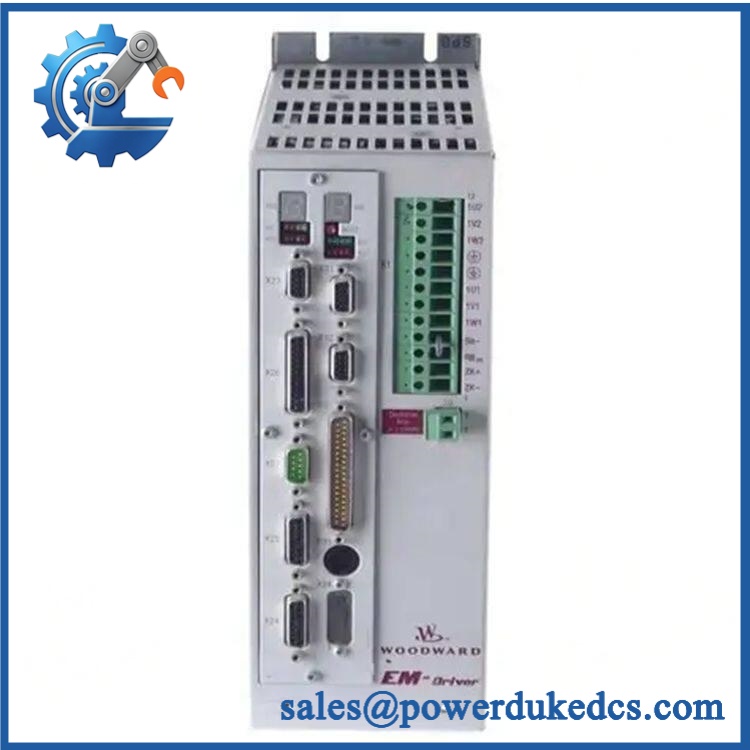
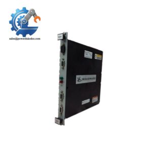
Woodward 3522-1005
Module 5: Quality Assurance & Testing SOP
1. Part Identity Verification
Record the complete 3522-1005 part number, serial number, hardware revision, manufacturer markings, and available date/lot information. Confirm that the unit is specifically configured for the EM-80 application.
2. OEM Anti-Counterfeit Visual Inspection
Inspect the enclosure, front-panel controls, terminals, labels, PCB markings, connectors, fasteners, and manufacturer identification. Compare construction details against known Woodward EM driver hardware.
3. Mechanical Inspection
Check the enclosure, connector interfaces, mounting holes, terminal blocks, cooling paths, and internal assemblies where accessible. Reject units showing corrosion, cracked boards, burned components, loose hardware, or unauthorized repair.
4. Electrical Pre-Test
Verify protective-earth continuity, supply-path integrity, connector condition, and absence of unintended shorts. Confirm that the power-stage components show no visible evidence of insulation breakdown or overheating.
5. Power-On Self-Test (POST)
Apply the specified control and power inputs in a controlled test environment. Verify the startup sequence, LCD/status indications, fault indications, and readiness state. Woodward’s EM driver uses a two-line LCD and keypad for monitoring and parameter access.
6. Motor / Actuator Interface Test
Connect the driver to a suitable EM-80 test actuator or approved simulator. Verify correct motor excitation, startup behavior, actuator movement, and absence of abnormal vibration or fault states.
7. Rotation-Direction Test
Command representative movement and confirm clockwise rotation for the 3522-1005 application. Record the commanded and observed direction before the unit is released.
8. Position Feedback Test
Verify resolver feedback and associated position signals. The EM-80/EM-300 system uses resolver-based position sensing, and the driver monitors this feedback for fault detection.
9. Analog Demand / Position Verification
Apply representative command signals and verify that actuator response follows the expected demand. The driver documentation identifies a 1–5 V position-readout output corresponding to the actuator’s 0–40° output-shaft travel; this signal is intended for indication, not closed-loop control.
10. Ready / Alarm Verification
Test the Ready-for-Use output and Common Alarm behavior. Confirm that fault conditions produce the expected status transitions and that reset behavior functions correctly.
11. Extended Burn-In
Operate the driver under representative motor and communications conditions. Monitor supply stability, fault status, temperature, resolver feedback, position response, and intermittent resets.
12. Final QC Record
Record hardware revision, serial number, input conditions, actuator test results, rotation direction, resolver status, alarm behavior, burn-in results, and final QC disposition. Package using suitable ESD and mechanical protection.
Module 6: Procurement & Lifecycle FAQ
Q1. Is Woodward 3522-1005 genuinely in stock, and what is the cutoff for emergency shipping?
Current independent supplier listings continue to show 3522-1005 as an available Woodward product, although these listings do not establish dependable real-time inventory. Because the part is legacy hardware and current documentation also describes newer retrofit drivers, physical stock and same-day dispatch capability should be confirmed before an emergency PO.
Q2. How do you guarantee the condition and authenticity of an obsolete or surplus 3522-1005?
Require complete part-number and revision verification, OEM-style visual inspection, earth-continuity testing, controlled power-up, status-panel verification, actuator-interface testing, resolver feedback testing, CW rotation verification, alarm testing, and documented burn-in.
Q3. Are there firmware or configuration issues I should warn my engineers about before issuing the PO?
Yes. The main concern is the driver application configuration, particularly actuator type and rotation direction. For a replacement involving newer 3522-1042 hardware, Woodward provides application-specific configuration procedures rather than treating the substitution as a simple hardware swap.
Q4. Can 3522-1042 replace 3522-1005 directly?
Not without configuration and retrofit checks. Woodward’s retrofit documentation specifically states that previous drivers including 3522-1005 can be replaced with 3522-1042, but the newer driver must be configured for the required application type and rotation direction.
Q5. What warranty and return terms should procurement require?
Specify a written functional warranty and RMA procedure covering power-up, status indication, actuator operation, resolver feedback, rotation direction, position response, and fault/alarm behavior. The PO should also define exclusions for incorrect motor wiring, incorrect rotation configuration, improper grounding, unsuitable supply power, and customer-side actuator faults.



 Start Chat


