

Description
Module 2: The 10-Second Procurement Snapshot
- Brand: ABB Bailey
- Full Model Number: IMDSO14
- Lifecycle Status: Legacy / INFI 90 spare
- Core Function: Digital output signal control
- Top 3 Technical Specs: INFI 90 architecture; digital outputs; discrete field-device control
- Stock & Condition: New Surplus / Tested Refurbished; physical stock confirmed before shipment
Module 3: Supply Chain & Technical Deep Dive
A failed digital output module can leave valves, contactors, relays, or other discrete field devices without their required control signal. ABB Bailey IMDSO14 belongs to the INFI 90 digital I/O family and is used where discrete output signals must be transferred from the control system toward field equipment. For a legacy installation, finding the exact spare is often more practical than redesigning the I/O architecture around a newer platform.
From an inventory standpoint, this is a classic low-frequency, outage-sensitive spare. Keep one tested unit when a single output-module failure could stop a production section. Exact channel count, output voltage/current ratings, isolation characteristics, and terminal-unit compatibility should be verified against the original hardware documentation before purchase. Do not substitute specifications from a similar IMDSO-series model.
Module 4: Migration, Compatibility & Field Traps
Replacement Matrix
| Approval Item | Assessment |
|---|---|
| Replacement Type | Direct replacement candidate for an existing IMDSO14 |
| Exact Part Match | IMDSO14 |
| System Family | ABB Bailey INFI 90 |
| I/O Function | Digital output |
| Software Compatibility | Verify existing INFI 90 configuration |
| Terminal Compatibility | Verify installed termination unit and wiring |
| Hardware Modification | Normally not required for an exact replacement |
| Engineering Approval | Required before commissioning |
⚠️ Field Trap 1 — Output Rating
Do not assume that every digital-output channel can drive the same load.
Before installation, identify whether each output drives a relay coil, solenoid, contactor, lamp, or another field device. Check the original module documentation for the applicable voltage and current limits.
⚠️ Field Trap 2 — Terminal Unit and Wiring
The I/O module is only one part of the signal path.
Before pulling the old module:
- Photograph the complete I/O assembly.
- Record the terminal-unit identification.
- Mark every field wire.
- Compare the wiring with the site drawing.
- Confirm the output channel assignment.
A connector that physically fits is not enough.
⚠️ Field Trap 3 — Energized Outputs
Be careful when restoring power. A digital output may immediately return to its configured state after the controller resumes operation.
For equipment such as motor starters or solenoid valves, verify the safe state before applying power.
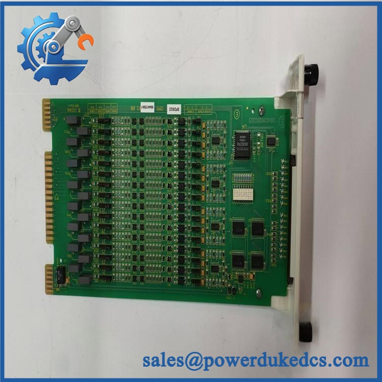
ABB IMDSO14
Module 5: Quality Assurance & Testing SOP
Digital output hardware should be tested with an appropriate load or simulated load. A simple power-up check is not sufficient.
1. OEM Identification Inspection
- Verify ABB Bailey identification.
- Confirm IMDSO14 marking.
- Record serial number and hardware revision.
- Inspect PCB and connectors.
- Check for corrosion, oxidation, cracked components, or repair marks.
- Inspect terminal-unit mating surfaces where applicable.
- Photograph the identification label.
2. Power-On Self-Test
Using a compatible INFI 90 test rack:
- Apply the specified system power.
- Observe startup behavior.
- Check RUN/ERR or applicable status indicators.
- Review diagnostic information.
- Monitor abnormal current draw.
- Check operating temperature.
3. Digital Output Test
Using a compatible test setup:
- Command each applicable output.
- Verify output-state changes.
- Apply a suitable simulated load.
- Measure the output response.
- Check ON/OFF behavior.
- Confirm that outputs return to the expected state after repeated switching.
Do not connect an unknown field load during bench testing.
4. Extended Functional Test
Record:
- Module status
- Output response
- Diagnostic status
- Load-test results
- Temperature behavior
- Communication status
- Test duration
Where required, retain the test readings with the unit’s serial number.
5. Final QC
- Part number recorded
- Serial number recorded
- Hardware revision recorded
- Power-on test completed
- Digital output test completed
- Load test completed where applicable
- Test report archived
- ESD packaging applied
- Protective cushioning installed
- QC label applied
Module 6: Procurement-Driven FAQ
1. Is ABB IMDSO14 physically in stock, and can it ship immediately?
Stock should be verified against the actual physical unit before confirming delivery. For an outage-critical requirement, confirm the quantity, condition, test status, and shipping cutoff at the time of order.
2. How do you verify the condition of a surplus ?
A proper inspection should include the OEM label, serial number, PCB condition, connectors, power-up behavior, diagnostics, and digital-output testing. For a tested unit, request the actual test report and photographs.
3. Can I directly replace my existing ?
An exact replacement is the preferred route, but the surrounding I/O hardware still needs verification. Check the terminal unit, wiring, channel assignments, configuration, and field-load requirements before installation.
4. What should my engineers check before powering the replacement?
Verify the output wiring and load first. A wrong connection can energize a field device unexpectedly when the controller enters its normal operating state. Confirm the safe state before power-up.
5. Should I keep an as buffer stock?
If the installed INFI 90 system controls production-critical equipment, yes. One tested spare is a reasonable Min/Max starting point. For a slow-moving legacy I/O module, holding several units can increase carrying cost and obsolescence exposure without providing much additional protection.











 Start Chat


