

Description
- Brand: ABB
- Full Model Number: REX010 / HESG324426R1
- Lifecycle Status: Legacy REG 316 / REG 216 protection-system component
- Core Function in System: Injection supply for 100% stator and rotor earth-fault protection
- Top 3 Hardcore Specs: 36–312 V DC U3 supply range; 96 V DC output; 1 A output
- Injection Frequency: 12.5 Hz or 15.0 Hz
- System Association: ABB REG 316 / REG 216 generator protection
- Physical Form: Dedicated injection unit installed in REG 316-type casing
- Condition & Lead Time: Legacy OEM or tested replacement stock; emergency availability subject to physical inventory confirmation
ABB documentation states that REX 010 supplies the injection transformer block REX 011 used for 100% stator and rotor ground-fault protection. Three versions are documented: U1, U2, and U3. For U3, the station-battery range is 36–140 V DC, with a 96 V DC, 1 A output. The injection frequency is selectable at 12.5 Hz or 15.0 Hz through the specified PCB jumper position.
Module 3: Technical Intro & Downtime Impact
At 3 AM, a generator ground-fault protection problem is not the time to discover that the injection source has no usable spare. The ABB REX010 is the dedicated injection supply that feeds the REX011 injection transformer block, which generates the signals used by the stator- and rotor-ground-fault protection scheme. Without that injection path, the associated 100% earth-fault protection test and operating functions can be compromised, forcing a generator protection outage or extended maintenance window. ABB explicitly describes REX010 as the power-supply unit for REX011.
The electrical variant matters. ABB specifies U1 at 110/125 V DC, U2 at 88–312 V DC with 96 V, 1 A output, and U3 at 36–140 V DC with 96 V, 1 A output. The injection frequency is set to one-quarter of the rated 50/60 Hz system frequency: 12.5 Hz or 15 Hz. The front panel also provides a READY indication, an OVERLOAD indication, a DISABLED indication, an enable/disable switch, and a reset function. (Do not substitute one REX010 voltage version for another simply because the enclosure and front panel look identical.)
Module 4: Dynamic Emergency Swap & Configuration Guide
1. Pre-Swap Prep — Identify the Voltage Variant First
Before shutdown, record the complete nameplate: REX010 HESG324426R1, voltage variant, serial information, and any associated REX011 identification. Confirm the station-battery voltage against the unit variant before disconnecting anything. ABB states that the input voltage and opto-coupler voltage are specified at order time and set at the works; there are no user adjustments inside the unit. Use LOTO, ESD protection, insulated tools, the generator protection schematic, and a calibrated DC multimeter.
2. Removal — Disable Injection Before Working on the Generator Star Point
Make the generator protection system safe under the plant switching procedure. ABB specifically requires the injection voltage to be switched off before work on the star point; the REX010 front switch must be placed in DISABLE, with the yellow DISABLED LED illuminated. Disconnect the auxiliary supply and external interfaces only after the injection system has been disabled, then release the unit from its REG 316-style mounting position and withdraw it without stressing the internal or external wiring.
3. Installation & Configuration — Preserve the Factory Voltage and Frequency Configuration
Install the replacement in the same mounting position and reconnect the supply and REX011 interfaces exactly to the original wiring diagram. Do not change internal PCB settings to force a different supply configuration. ABB states that the input voltage, injection frequency, and opto-coupler voltage are factory-specified and set before delivery. Where the installed system uses the frequency-selection jumper, verify the original documented position: X12 = 12.5 Hz and X11 = 15.0 Hz.
4. Power-On Self-Test (POST) — Check READY, OVERLOAD, and DISABLED States
Apply the correct auxiliary DC supply under controlled conditions. During normal operation, ABB specifies that only the green READY LED should be illuminated. A red OVERLOAD indication means the internal protection has operated and injection has been interrupted; the yellow DISABLED indication confirms that injection has been disabled. Confirm that the protection circuit resets correctly, verify the injection signal at the approved test point, and perform the generator protection functional test with the associated REX011 before releasing the machine.
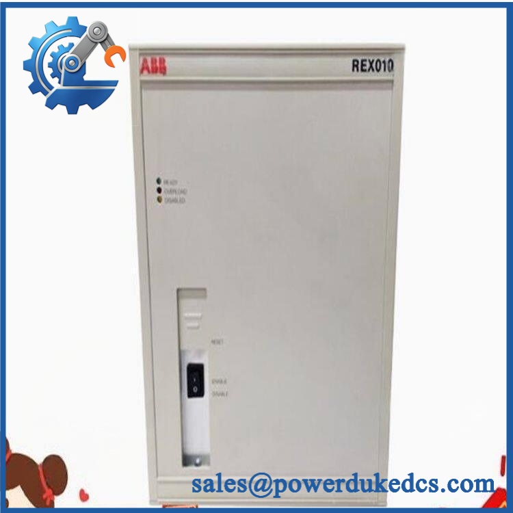
ABB REX010 HESG324426R1
Module 5: Quality Assurance & Testing SOP
The HESG324426R1 requires a controlled electrical test because the wrong supply variant can produce a serious commissioning error.
- Identity verification: Record ABB designation, HESG324426R1, serial number, voltage variant, revision information, and associated REX011 configuration.
- OEM anti-counterfeit visual inspection: Examine enclosure markings, front-panel labels, PCB identifiers, connectors, switchgear, and manufacturing details against known ABB construction.
- Mechanical inspection: Check the REG 316-style housing, mounting points, terminal blocks, connectors, fuse area, and enclosure for corrosion, contamination, impact damage, or overheating.
- Power-on self-test (POST): Apply the correct documented auxiliary voltage and verify the expected READY, OVERLOAD, and DISABLED indication behavior. ABB states that only READY should be lit during normal operation.
- Supply-range verification: Verify that the installed variant matches the required station-battery range; for U3, ABB specifies 36–140 V DC input and 96 V, 1 A output.
- Output verification: Measure the output under the approved test condition and confirm the expected nominal output for the specific version.
- Frequency verification: Confirm the configured injection frequency is 12.5 Hz or 15.0 Hz, as required by the installed protection scheme.
- Overload protection test: Verify the protective response using an approved controlled test method and confirm that injection is interrupted when the protection threshold is reached. ABB documents protection operation for excessive feedback from the generator.
- Reset test: Confirm operation of the front-panel RESET function and verify that the fault condition must be removed before successful reset.
- interface verification: Check the complete -to- signal path and confirm the transformer block receives the correct injection supply.
- Extended runtime test: Monitor the unit under controlled load for thermal rise, intermittent READY loss, nuisance overload operation, or unstable injection output.
- Final QC record: Retain identification photographs, supply measurements, frequency measurements, LED-status results, test duration, technician sign-off, and pass/fail disposition.
ABB’s manual also states that defective U2 and U3 units are to be returned to ABB or an authorized ABB agent for repair, reinforcing the importance of using the correct factory-configured variant rather than performing ad-hoc internal modification.
Module 6: Maintenance & Reliability FAQ
1. Is ABB HESG324426R1 a direct drop-in replacement, or does it require a firmware flash?
This is not primarily a firmware-replacement issue. is an injection power unit rather than the main generator-protection processor. The critical compatibility checks are the exact part number, voltage variant, injection frequency, opto-coupler configuration, and associated transformer arrangement. ABB states that these parameters are specified and set at the factory.
2. Is it safe to hot-swap the while the system is running?
No. Do not treat as a hot-swappable device. ABB explicitly requires the injection voltage to be switched off before work is performed on the generator star point, with the switch in DISABLE and the yellow DISABLED LED illuminated. Follow the site’s generator-protection isolation and switching procedure before removal.
3. Will replacing cause my current protection program to be lost?
Replacing does not normally erase the protection application’s settings because provides the injection supply rather than acting as the primary protection processor. The safer procedure is still to back up the associated protection configuration, record the present injection frequency and wiring, and retain the identification before intervention.
4. What should I verify after installing the replacement unit?
Verify the correct voltage variant, normal READY indication, absence of OVERLOAD, correct DISABLED behavior, correct injection frequency, and proper interaction with . ABB documents the specific LED meanings and the factory-defined input/output characteristics, so acceptance testing should be based on measured behavior rather than appearance alone.
5. What are the warranty terms if the unit fails post-installation?
Warranty should follow the commercial terms for the exact unit and condition supplied. For this legacy protection component, retain the serial number, pre-shipment test results, supply-voltage measurements, installation date, commissioning record, and any overload or fault indications. Those records are particularly useful when separating an fault from an external , wiring, generator star-point, or ground-fault protection problem.











 Start Chat


