

Description
- Brand: ALSTOM
- Full Model Number: AH116-2
- Lifecycle Status: Legacy / EOL availability
- Core Function: High-level analog signal input module
- Top 3 Technical Specs: 8 channels; 0 to +5 V, +1 to +5 V, 0 to +10 V; 0 to 20 mA / 4 to 20 mA
- Stock & Condition: Availability to be confirmed; New Surplus subject to lot verification
Supply Chain & Technical Deep Dive
A failed legacy I/O module can leave an otherwise serviceable Alspa control system short of critical process signals. ALSTOM AH116-2 is identified in an Alspa P320 system-definition document as an 8-channel high-level input module. The documented signal ranges include 0 to +5 V, +1 to +5 V, 0 to +10 V, 0 to 20 mA, and 4 to 20 mA, with channel isolation specified for the AH116-2 entry. That makes the exact part number important when replacing an installed board; a visually similar I/O card can have a different signal direction or electrical function.
From a TCO perspective, retaining the existing Alspa architecture can avoid unnecessary panel rewiring and a larger control-system replacement. Eight analog channels allow one module to service multiple process measurement points, while configurable voltage and current inputs support different transmitter arrangements documented for the Alspa platform. Public secondary listings do not agree on every AH116-2 specification, with some incorrectly describing it as an analog-output or other control board. For that reason, values such as power consumption, exact terminal arrangement, dimensions, and detailed conversion performance should be verified against the customer’s installed documentation and physical board before purchase.
Migration, Compatibility & Field Traps
Replacement Matrix
| Replacement Type | Assessment | Engineering Requirement |
|---|---|---|
| Drop-in Replacement | Yes for an exact AH116-2 match | Confirm complete part number, board revision, rack type, connector layout, and approved I/O configuration |
| Software Compatible | System-dependent | Verify Alspa controller configuration, I/O database, and channel assignments before commissioning |
| Hardware Modification | Not expected for an exact replacement | Alternate hardware requires documented electrical and mechanical equivalence |
Field Traps: Watch Out
Signal-direction confusion: Some current secondary listings classify AH116-2 as an analog-output or general control module, while the Alspa system-definition documentation identifies it as an 8-channel high-level input module. Do not connect a field transmitter or control actuator until the installed documentation and board markings confirm the intended signal direction.
Range configuration: The documented input ranges include 0 to +5 V, +1 to +5 V, 0 to +10 V, 0 to 20 mA, and 4 to 20 mA. Confirm the channel configuration before reconnecting field wiring. A transmitter configured for 4 to 20 mA should not be assumed to match a voltage-configured channel.
ESD exposure: Remove the module only under controlled ESD conditions. Protect edge connectors and avoid placing the PCB on conductive or unapproved work surfaces.
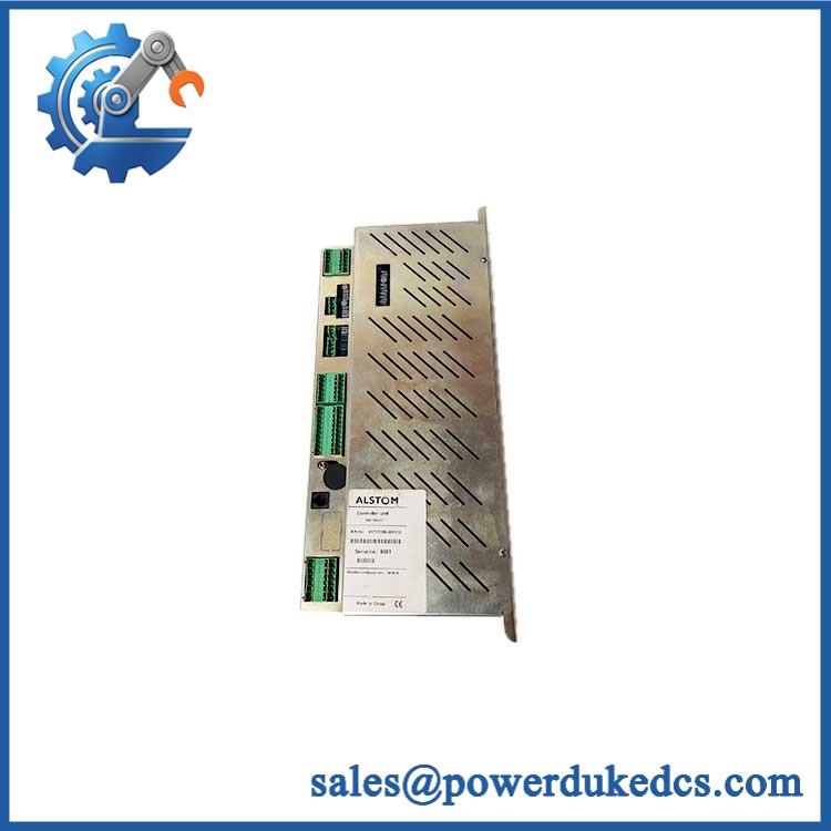
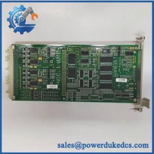
ALSTOM AH116-2
Quality Assurance & Testing SOP
The pre-shipment inspection should treat each as an individually traceable industrial board.
OEM identification inspection
Verify ALSTOM markings, complete designation, board revision where present, serial information where available, and label consistency against the purchase order.
OEM anti-counterfeit visual inspection
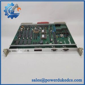
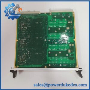
Inspect PCB markings, component layout, connector geometry, solder quality, labels, fasteners, and evidence of unauthorized component replacement or board-level rework.
Physical condition inspection
Check for corrosion, contamination, cracked solder joints, bent contacts, damaged connectors, overheated components, missing hardware, and mechanical deformation.
Power-on self-test
Where the correct Alspa test environment is available, power the board under controlled conditions and record startup behavior and applicable diagnostic indicators. Record any ERR, RUN, fault, or channel-status indication provided by the installed platform.
Analog input simulation
Apply controlled test signals across the documented input ranges, including representative 4 to 20 mA and voltage signals where the test fixture supports them. Confirm channel response and configuration against the approved test procedure.
I/O load testing
Use an approved I/O test fixture to verify the module under representative connected conditions. For analog-input applications, this should be performed through controlled signal sources and simulated transmitter loads rather than directly connecting live plant instrumentation.
Channel isolation verification
Where the test setup supports it, verify the documented channel-isolation behavior and check for unintended interaction between adjacent channels.
Final traceability record
Store identification photographs, board revision data, test results, physical-condition findings, packaging inspection, and shipment records against the individual unit. Failed units should be quarantined.
Procurement-Driven FAQ
Is the ALSTOM genuinely in stock, and what is the overnight shipping cutoff?
Physical availability should be confirmed against the actual warehouse lot before order release. Overnight cutoff depends on inspection completion, destination, and carrier collection time. For outage-driven orders, the quotation should state the confirmed dispatch time rather than a generic shipping promise.
How do you verify the condition of obsolete or surplus modules?
The unit should pass part-number verification, PCB inspection, connector inspection, and controlled functional testing where the required Alspa test environment is available. New-surplus inventory should also be checked for storage-related corrosion, contamination, and prior-repair evidence.
What are the warranty terms and return rules for defective units?
Warranty duration and return conditions should be documented on the quotation before purchase. A defect claim should include the part number, revision or serial information where available, installation status, test conditions, and observed fault symptoms so the unit can be matched to its outbound inspection record.
Are there firmware compatibility issues my engineers should check?
Yes. The board itself is part of a larger Alspa control architecture, so the controller configuration, I/O database, channel assignments, and system revision should be checked before commissioning. Public documentation confirms the within the Alspa P320 I/O architecture but does not establish one universal firmware requirement for every installation.
Can another ALSTOM module replace ?
Do not assume interchangeability. The documented Alspa module list separates from other analog-input and analog-output modules, including AH116-1, AS111-1, AS111-2, and AS112. Their signal functions and electrical characteristics differ. An alternate module should be accepted only after the installed system documentation confirms equivalence.



 Start Chat


