

Description
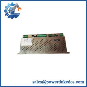
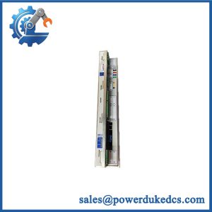
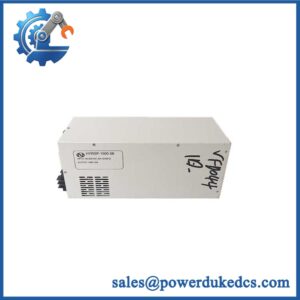
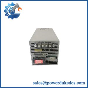
- Brand: ALSTOM
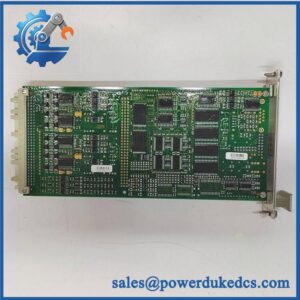
- Full Model Number: 029.144.440
- System/Series Family: Alstom industrial/railway control hardware
- Core Function: Product-specific control or interface module requiring configuration verification
- Top 3 Hardcore Specs: Exact part-number identification required | Legacy Alstom hardware | Application-specific interface
- Electrical Rating: Verify from nameplate and technical documentation
- Communication Interface: Verify from exact hardware revision
- Installation Type: Verify from installed system
- Stock Status: New surplus, factory sealed, or fully tested refurbished subject to exact inventory confirmation
Identification note: Publicly indexed technical documentation for ALSTOM 029.144.440 is insufficient to establish a reliable function, electrical specification, or system-family designation. The part number should therefore not be assigned a specific CPU, I/O, relay, or communication function without additional nameplate or manufacturer documentation.
Module 3: Technical Product Introduction
A legacy Alstom spare cannot be identified safely from a numeric reference alone when the available documentation does not establish its exact hardware function. ALSTOM 029.144.440 should be treated as an application-specific spare until the complete nameplate, associated equipment, or original technical documentation confirms whether it is a control, interface, power, protection, or other module.
For procurement and replacement purposes, the 029.144.440 reference itself should be preserved exactly, including punctuation. Do not substitute a visually similar Alstom assembly based only on dimensions or connector arrangement. —For older railway and industrial control equipment, hardware revisions and application-specific variants can differ internally while retaining similar external packaging.
Module 4: Application Scenarios & Field Realities
- During replacement of an installed Alstom control assembly, record the complete identification plate, revision code, serial number, connector layout, and cabinet location before removal. Those details can be more useful than the shortened commercial reference.
- For railway control equipment, verify the parent system and vehicle or application designation before selecting a spare. Environmental, power-supply, and functional requirements can be specific to the installed rolling-stock or control architecture.
- When the original module is no longer available for comparison, photograph every connector and terminal marking. A correct mechanical fit does not establish electrical or software compatibility.
- For an urgent maintenance requirement, provide the complete part marking rather than only “029.144.440.” Any additional Alstom assembly number, PCB number, revision, or equipment reference can materially improve identification accuracy.
Module 5: Migration, Compatibility & Installation Traps
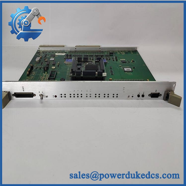
ALSTOM 029.144.440
Replacement Matrix
| Replacement Type | Assessment | Engineering Requirement |
|---|---|---|
| Drop-in Replacement | Unconfirmed | Verify complete part number, revision, electrical rating, connectors, and parent system |
| Software Compatible | Unconfirmed | Verify firmware, configuration data, and system-specific software requirements |
| Hardware Modification Required | Unknown | Determine exact module function and interface before installation |
Field Traps — Watch Out
1. Do not infer the function from the part number: There is insufficient reliable public documentation to establish that 029.144.440 is a particular Alstom CPU, I/O, relay, or communication module.
2. Check the complete identification: If the physical unit carries additional markings such as a PCB number, assembly designation, revision, or equipment reference, those should be retained when ordering.
3. Connector compatibility is not functional compatibility: A replacement with identical connectors can still have different internal circuitry, firmware, or electrical characteristics.
4. Verify the parent system: Before commissioning, confirm the exact Alstom equipment in which the module is installed and compare the replacement against the original technical documentation.
Module 6: Quality Assurance SOP
Before shipment, each ALSTOM 029.144.440 should undergo a documented identification and hardware inspection sequence.
- Step 1 — Part-number verification: Record 029.144.440, all additional assembly numbers, serial number, hardware revision, PCB markings, and manufacturing information.
- Step 2 — OEM anti-counterfeit visual inspection: Examine Alstom labels, logos, PCB markings, connectors, terminal blocks, component markings, and manufacturing identifiers. Photograph the complete nameplate.
- Step 3 — Physical condition inspection: Check the enclosure, PCB, connectors, terminals, mounting hardware, and exposed components for corrosion, contamination, cracks, bent contacts, loose hardware, or evidence of previous repair.
- Step 4 — Electrical identification: Confirm the rated supply voltage and interface requirements from the actual nameplate or verified technical documentation before energizing the unit.
- Step 5 — Power-on self-test (POST): Where the module’s function and approved test procedure are known, energize it under controlled conditions and record startup indications, diagnostic LEDs, display behavior, and fault messages.
- Step 6 — Interface verification: Test applicable I/O, communication, relay, or control interfaces only after the exact module function has been established from technical documentation.
- Step 7 — Communication handshake verification: If the module contains a communication interface, establish a controlled connection using the applicable protocol and verify representative data exchange.
- Step 8 — Configuration verification: Compare hardware revision and configuration information with the customer’s original unit before releasing the module for installation.
- Step 9 — Final photographic record: Photograph the complete module, nameplate, serial number, PCB markings, connectors, mounting interfaces, and final packaging.
QA release criterion: Because reliable public technical data for ALSTOM 029.144.440 could not be established, it should not be advertised with unverified electrical specifications, communication protocols, dimensions, weight, or a specific control-system function. Final functional testing should be based on the exact Alstom documentation or a known-good reference unit.



 Start Chat


