

Description
- Brand: ALSTOM / Converteam
- Full Model Number: PIB100G
- Associated Part Number: 3BEE0226
- Product Type: Power Interface Board
- System/Series Family: ALSTOM / Converteam industrial control systems
- Core Function: Power distribution and interface circuitry for compatible control-system electronics
- Top 3 Hardcore Specs: 1-digit display | CAN bus interface | Serial communication ports
- Interface: CAN bus and serial ports
- Display: 1-digit diagnostic display
- Stock Status: New surplus / condition to be confirmed per available unit
Module 3: Technical Product Introduction
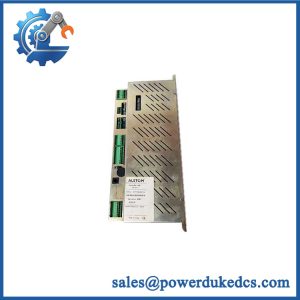
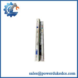
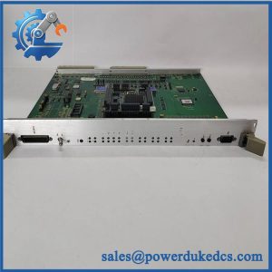
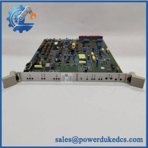
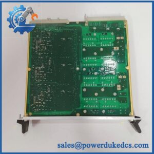
A failed power-interface board can leave an otherwise serviceable control rack without the required power distribution or communication path. ALSTOM PIB100G, commonly referenced with 3BEE0226, is identified as a Power Interface Board used in ALSTOM/Converteam control equipment. Available product documentation identifies a 1-digit display, CAN bus, receiver/transmitter ports, and serial communication ports on this assembly.
The important replacement characteristics are therefore not simply physical dimensions. The PIB100G combines power-interface and communication functions within the associated control architecture. Exact input voltage, regulated outputs, connector pinout, and system compatibility should be confirmed against the installed equipment documentation; published third-party specifications for this legacy board are inconsistent. —Do not approve a substitution based solely on the PIB100G name.
Module 4: Application Scenarios & Field Realities
- In ALSTOM/Converteam control cabinets, the PIB100G provides the interface layer required by associated control electronics. A replacement should be evaluated together with its connected communication and power circuits.
- When a control rack loses communication after a power event, inspect the PIB100G and its associated CAN/serial wiring along with the upstream supply. A board replacement alone may not correct a damaged communication transceiver or cable.
- During planned maintenance, record the original connector positions and communication topology before removing the board. The available documentation specifically associates the with CAN bus and serial communication interfaces.
- For legacy Converteam equipment, retaining the exact interface-board configuration can be preferable to redesigning the control cabinet around a newer platform. Verify the complete equipment model and associated 3BEE0226 identifier before procurement.
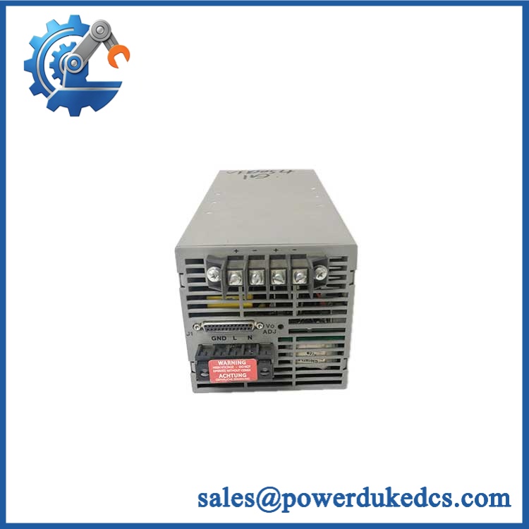
ALSTOM PIB100G 3BEE0226
Module 5: Migration, Compatibility & Installation Traps
Replacement Matrix
| Replacement Type | Assessment |
|---|---|
| Drop-in Replacement | Yes, when replacing the same / 3BEE0226 configuration in compatible ALSTOM/Converteam equipment |
| Software Compatible | Configuration-dependent; associated CAN/serial parameters and control-system configuration must be verified |
| Hardware Modification Required | Not expected for an exact replacement; required if connector, power, communication, or board revision differs |
Field Traps — Watch Out
1. Match and 3BEE0226 together.
Multiple references identify 3BEE0226 as the associated alternate part number for . Verify both identifiers against the installed board.
2. Do not assume published power specifications are interchangeable.
Third-party listings provide conflicting electrical specifications for this legacy board. Confirm the actual cabinet supply and board documentation before energization.
3. Check CAN and serial wiring.
Inspect connector seating, cable shielding, termination, and communication topology before condemning the PCB. A communication fault can originate outside the board.
4. Record the original configuration.
Photograph the board, connectors, display position, and cable routing before removal. This is particularly useful when servicing older ALSTOM/Converteam cabinets with limited documentation.
Module 6: Quality Assurance SOP
Before shipment, each available ALSTOM / 3BEE0226 should pass a documented inspection sequence:
- OEM identification inspection — Verify ALSTOM/Converteam markings, designation, 3BEE0226 identification, revision information, and board labels.
- OEM anti-counterfeit visual inspection — Examine PCB construction, component markings, connectors, labels, display assembly, solder workmanship, and evidence of unauthorized modification.
- Physical inspection — Check the PCB, connector interfaces, mounting points, display, communication ports, and power-interface components for corrosion, cracking, contamination, or mechanical damage.
- Part-number verification — Confirm the physical board against the exact requirement before electrical testing.
- Controlled power-on test — Apply the verified supply using a protected laboratory test fixture and monitor startup current and board status.
- Display verification — Confirm the 1-digit display initializes correctly and responds as expected within the available test environment.
- Power-interface verification — Measure applicable power paths and regulated outputs against the approved technical specification.
- CAN bus handshake verification — Connect the board to a compatible CAN test environment and verify communication, node response, and data exchange where supported.
- Serial-interface verification — Test applicable serial receiver/transmitter ports using a controlled communications fixture.
- Diagnostic verification — Check available board-level status indications and confirm the absence of unexpected hardware faults.
- Extended stability test — Operate the board under controlled conditions and monitor power stability, communications, display behavior, and abnormal temperature.
- Final visual inspection — Recheck connectors, labels, display, mounting features, and PCB condition after testing.
- Test record and packaging — Record the model, associated part number, revision, test results, inspection date, and packaging condition before dispatch.
QA note: The should not be validated solely through a power-on test. Because available documentation identifies CAN bus, serial communication, and display functions, those interfaces should be tested wherever a compatible laboratory fixture is available.



 Start Chat


