

Description
- Brand: ALSTOM
- Full Model Number: 029.147.908
- System/Series Family: ALSTOM Legacy Industrial Control Electronics
- Core Function: ALSTOM industrial control assembly identified by part number 029.147.908
- Top 3 Hardcore Specs: ALSTOM part number 029.147.908; legacy control-system hardware; exact electrical function requires nameplate or system documentation
- Stock Status: New Surplus — exact hardware revision and system application to be confirmed
Module 3: Technical Product Introduction
The ALSTOM 029.147.908 is a legacy industrial automation component identified by its ALSTOM part number. Publicly accessible technical documentation for this exact number is extremely limited, and I could not verify a reliable manufacturer datasheet establishing its precise function, I/O architecture, supply voltage, communications interface, dimensions, or operating temperature. For a replacement project, the complete 029.147.908 identification should therefore be treated as the primary procurement reference.
That distinction matters with older ALSTOM control equipment. A three-part numerical code may identify a specific board, assembly, or configured spare rather than a complete product family. No responsible replacement specification should be inferred from the part number alone. The original equipment nameplate, PCB markings, connector arrangement, and host-system manual should be used to establish the electrical and functional requirements before installation.
Module 4: Application Scenarios & Field Realities
- During maintenance of an older ALSTOM control cabinet, record every marking on the original assembly before removal. Secondary PCB revision codes can be essential when the base part number appears in multiple equipment generations.
- For an emergency spare-parts requirement, compare the replacement against the installed hardware at connector level. Physical dimensions alone are not sufficient evidence of electrical compatibility.
- When the original control system is still operational, capture its configuration and diagnostic information before removing the suspect assembly. This provides a useful baseline for post-installation verification.
- If the component is being used in a protection or process-control chain, verify its actual role from the system drawing before procurement. The available public evidence does not establish whether 029.147.908 is an I/O, processing, interface, power, or protection assembly.
Module 5: Migration, Compatibility & Installation Traps
Replacement Matrix
| Replacement Type | ALSTOM 029.147.908 Assessment | Engineering Requirement |
|---|---|---|
| Drop-in Replacement | Potentially yes for an exact part-number and revision match | Verify PCB revision, connectors, electrical ratings, and host-system compatibility |
| Software Compatible | Not established | Determine whether the assembly contains firmware or configuration-dependent electronics |
| Hardware Modification Required | Unknown for alternative parts | Do not substitute another ALSTOM assembly without engineering verification |
Field Trap 1 — Part-number ambiguity:
The available public information does not establish the exact electrical specification of 029.147.908. Do not infer supply voltage, I/O type, communication protocol, or pinout from the numerical designation.
Field Trap 2 — Revision mismatch:
Legacy industrial assemblies can have later PCB revisions while retaining closely related base identification. Compare the complete label, revision code, connector layout, and board markings against the installed unit before accepting a replacement.
Installation note: De-energize the equipment according to the approved maintenance procedure. Use ESD protection, document connector orientation, verify the host-system power supply, and compare the replacement pinout against the original before applying power.
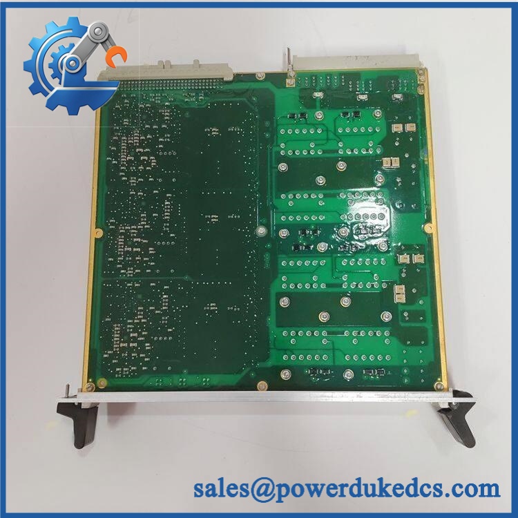
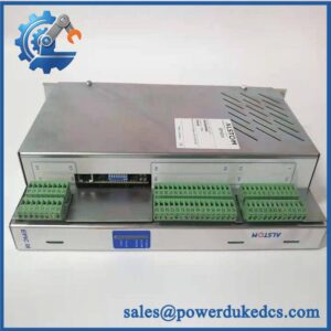
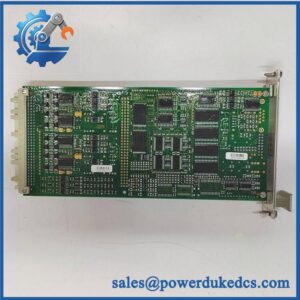
ALSTOM 029.147.908
Module 6: Quality Assurance SOP
- OEM identification inspection — Verify ALSTOM 029.147.908, all secondary markings, serial information, revision codes, and manufacturing labels.
- Physical PCB inspection — Examine connectors, terminal points, mounting hardware, PCB surfaces, components, solder joints, and protective coatings for corrosion, cracking, contamination, overheating, or previous repair.
- OEM anti-counterfeit visual inspection — Compare ALSTOM labeling, PCB construction, connector geometry, component placement, board markings, and manufacturing identifiers against authenticated reference hardware.
- Electrical specification verification — Establish the correct supply voltage, current requirement, pinout, signal levels, and grounding arrangement from the original equipment documentation or verified reference unit before applying power.
- Power-on self-test (POST) — Where a compatible test fixture is available, energize the assembly under controlled conditions and check diagnostic indicators, current consumption, startup behavior, and host-system recognition.
- I/O verification — If the assembly is confirmed to contain I/O circuitry, test each applicable channel using calibrated signal sources and compare the results with the approved reference values.
- Communication handshake verification — If a communications interface is confirmed, establish communication with the appropriate ALSTOM host system and verify stable data exchange.
- Functional test — Reproduce the assembly’s actual operating function using an approved system-level test procedure rather than relying only on a power-up test.
- Thermal observation — Monitor the assembly during extended operation for abnormal current draw, localized heating, unstable signals, or unexpected diagnostic behavior.
- Final traceability record — Photograph the complete identification label and PCB markings, record the inspection and functional-test results, and package the assembly using ESD-safe protective material.
Procurement note: The ALSTOM 029.147.908 should not be assigned unsupported technical specifications. I could not locate a reliable public manufacturer document that definitively identifies its exact function or electrical characteristics. For a production replacement, the safest matching criteria are the complete part number, PCB revision, connector arrangement, original equipment model, and nameplate information.



 Start Chat


