

Description
- Model: V4561484-0100
- Brand: ALSTOM
- Series: V4561484 series
- Core Function: IGBT gate-drive signal control
- Type: Gate Driver PCB / Power Electronics Board
- Key Specs: 800–1000 mA gate-drive classification; PCB assembly; industrial power-electronics application
Product Introduction
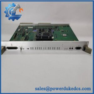
ALSTOM V4561484-0100 is identified in public trade data as a gate driver board for IGBT power electronics, rather than a general-purpose control or communication board. Its function is associated with driving IGBT switching devices and supporting the control stage of industrial power-conversion equipment.
For replacement work, the part number matters more than the board’s external appearance. Publicly available information specifically associates V4561484-0100 with an 800–1000 mA IGBT gate-driver application. Detailed electrical ratings, connector pinout, firmware requirements, and supported equipment should be confirmed against the equipment documentation or the original board before installation.
Key Technical Specifications
| Parameter | Specification |
|---|---|
| Manufacturer | ALSTOM |
| Model / Part Number | V4561484-0100 |
| Component Type | IGBT Gate Driver Board |
| Board Type | PCB Assembly |
| Primary Function | IGBT gate-drive signal control |
| Gate-Drive Classification | 800–1000 mA |
| Application | Industrial power electronics |
| Product Series | V4561484 series |
| Communication Protocol | Not publicly verified |
| Operating Voltage | Not publicly verified |
| Operating Temperature | Not publicly verified |
| Dimensions / Weight | Not publicly verified |
Important: Do not use generic voltage, temperature, connector, or dimensional data from unrelated ALSTOM boards as specifications for -0100. The available public evidence does not establish those values.
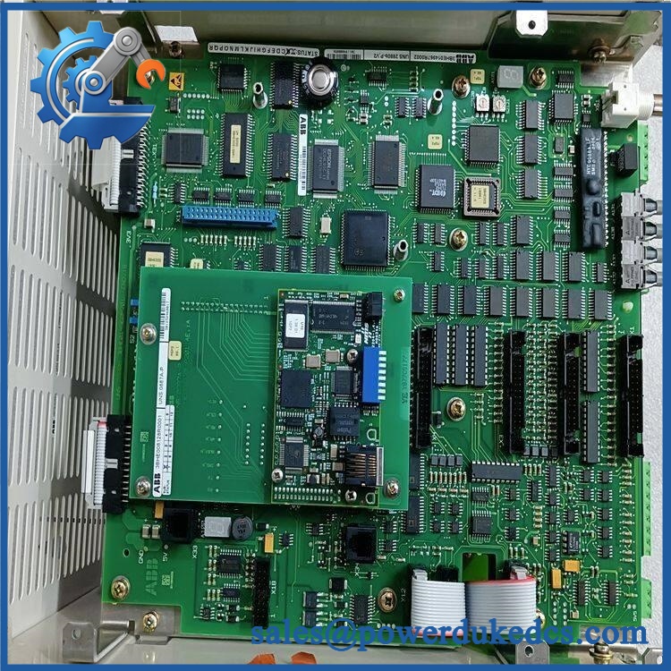
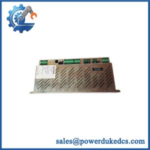
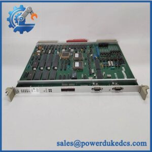
ALSTOM V4561484-0100
Application and Replacement Notes
-0100 is most relevant where an existing ALSTOM power-electronics assembly uses this specific gate-driver board. The gate-driver stage is electrically sensitive: incorrect gate timing, drive level, connector assignment, or protection configuration can affect IGBT switching behavior and may damage downstream power components.
For a replacement, check the following before installation:
- Confirm the complete part number.
- Compare PCB revision and component layout with the installed board.
- Record connector positions and wiring before removal.
- Verify the associated IGBT module and gate-drive interface.
- Check the original equipment documentation for electrical ratings.
- Confirm any board-level jumpers or configuration settings.
- Perform appropriate insulation and functional checks before returning the equipment to service.
Who Should Consider This Part?
This board is primarily relevant to MRO teams, industrial automation engineers, power-electronics maintenance engineers, and OEM/EPC procurement teams maintaining equipment that already specifies -0100.
It is not recommended to select this board solely because another ALSTOM PCB has a similar physical format. Gate-driver boards are application-specific, and connector similarity does not establish electrical interchangeability.
Inspection and Quality Control
For a stocked replacement board, the inspection sequence should include:
- Inbound inspection
- Verify source documentation and part-number traceability.
- Check the board label and serial number where applicable.
- Inspect for corrosion, scratches, discoloration, cracked components, or previous repair marks.
- Verify included accessories against the applicable packing documentation.
- Functional inspection
- Inspect connectors, terminals, PCB traces, and power components.
- Where a compatible test setup is available, perform controlled power-up and functional testing.
- Record test results in a Test Report.
- Electrical inspection
- Check grounding continuity where applicable.
- Perform insulation testing where the equipment procedure permits.
- Apply hipot testing only when supported by the manufacturer’s maintenance procedure.
- Configuration verification
- Record PCB revision.
- Photograph DIP switches or jumpers if present.
- Record any identifiable configuration information before shipment.
- Final packaging
- Use ESD protection.
- Seal the PCB in an anti-static bag.
- Add protective cushioning and a rigid carton.
- Record QC status and inspection date.
Test photographs or videos can be provided when available.
Technical Pitfalls to Check Before Replacement
Firmware mismatch:
For a gate-driver PCB, firmware may not be the primary compatibility factor, but associated control electronics can still impose revision requirements. Verify the complete equipment configuration rather than assuming every revision is interchangeable.
Connector and pinout differences:
This is a major risk. Two boards can have similar dimensions while using different pin assignments. Always compare the wiring diagram and connector designation.
IGBT compatibility:
The gate-driver stage must correspond to the associated IGBT power module and control circuit. A replacement board should not be selected only from the PCB model number of a neighboring assembly.
Configuration settings:
If the board contains jumpers, switches, or adjustable parameters, photograph the original configuration before removal and reproduce it on the replacement where applicable.
ESD protection:
Use a grounded wrist strap and ESD-safe work surface when handling the PCB. Gate-drive electronics can be damaged by electrostatic discharge even when no visible damage appears.
Related Models
Publicly indexed ALSTOM references associated with the same or related spare-parts listings include:
- ALSTOM PIB100G
- ALSTOM PIB101C
- ALSTOM PIB102A
- ALSTOM PIB310
- ALSTOM PIB903
These references should not be treated as direct electrical substitu without equipment-level compatibility verification.
Quick Conclusion
- is publicly identified as an IGBT gate-driver board.
- Public trade information associates it with an 800–1000 mA gate-drive classification.
- Exact voltage, temperature, connector, dimensions, and interchangeability data are not sufficiently verified from the available sources.
- For replacement, match the complete part number, PCB revision, connector pinout, and associated IGBT assembly.
- For procurement, request a clear photo of the actual board label and PCB revision before approving a substitute.
FAQ
What is?
It is a PCB identified in public trade data as an IGBT gate-driver board used in industrial power-electronics applications.
an amplifier module?
Some online listings describe the part as an amplifier module, but the stronger product-identification evidence located in trade data identifies as a gate-driver IGBT board. The application should therefore be verified against the original equipment documentation before publication or replacement.
What is the gate-drive rating?
Public trade data associates the part with an 800–1000 mA IGBT driver board. This should not be interpreted as a complete electrical specification; the actual drive voltage and other parameters require OEM documentation.
Can another ALSTOM board ?
Not automatically. A similar ALSTOM board or another -series reference should only be considered after checking the electrical interface, PCB revision, connector pinout, associated IGBT module, and equipment documentation.
Is the exact operating temperature known?
Not from the reliable public information reviewed here. Do not publish a specific operating-temperature range without an OEM datasheet or equipment manual.
suitable as an industrial spare?
Yes, when the equipment BOM or service documentation specifies this exact part number. For procurement, matching the original part number is the safest starting point.



 Start Chat


