

Description
- Model: V4561983-0100
- Brand: ALSTOM
- Series: ALSTOM High-Frequency Power System
- Core Function: Drives IGBT power-switch circuitry
- Type: IGBT driver / power control board
- Key Specs: 85 kV system application; 1,200 mA reported unit rating; industrial power electronics
- Condition: Availability and condition must be confirmed for the specific unit
- Identification: Verify PCB marking, revision, and serial number before purchase
Product Introduction
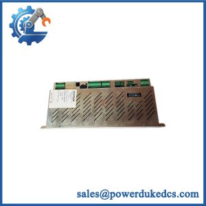
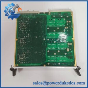
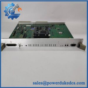
ALSTOM V4561983-0100 is an industrial IGBT driver board associated with ALSTOM high-frequency power equipment. Its reported application is an 85 kV / 1,200 mA high-frequency unit, where the board controls the switching interface of the power electronics section.
The important point for procurement is identification. This is not a generic PLC I/O card. Board revision, connector arrangement, and the associated power-system configuration must match the installed equipment. For a replacement purchase, confirm the nameplate and PCB markings against the original unit first. Reported electrical ratings should be treated as reference data and checked against the original ALSTOM documentation.
Key Technical Specifications
| Parameter | Specification |
|---|---|
| Manufacturer | ALSTOM |
| Model | V4561983-0100 |
| Product Type | IGBT driver / power control board |
| Application | High-frequency power equipment |
| Reported System Rating | 85 kV |
| Reported Current Rating | 1,200 mA |
| Main Function | IGBT switching control |
| Technology | Power electronics |
| Installation | Equipment-specific board assembly |
| Communication Interface | Not confirmed |
| Supply Voltage | Not confirmed |
| Operating Temperature | Not confirmed |
| Dimensions | Must be verified from physical unit |
| Weight | Must be verified from the supplied unit |
| Firmware | Board/revision dependent; verify before replacement |
| Documentation | Original ALSTOM documentation should govern final specifications |
Specification note: Publicly available references for this part are limited and inconsistent. Do not assume a generic PLC interface, 24 VDC supply, Ethernet port, or fieldbus protocol without checking the actual board and system drawings.
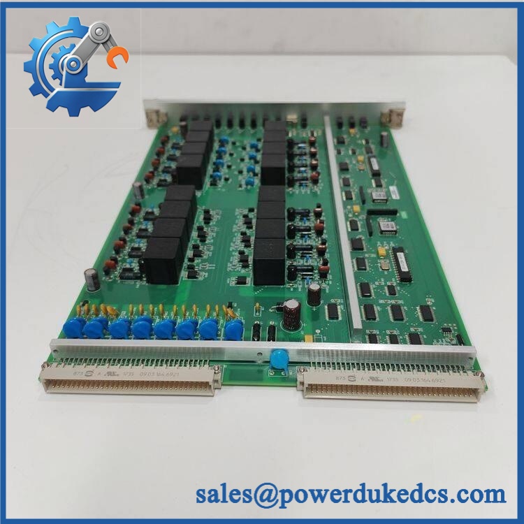
ALSTOM V4561983-0100
Stocking Recommendation
For a plant where this board controls a production-critical high-frequency power unit, one tested spare can be justified as buffer stock. Two units may make sense only when the replacement lead time is long and the cost of an extended outage materially exceeds the carrying cost.
| Inventory Factor | Recommendation |
|---|---|
| Criticality | High if installed in a production-critical power system |
| Minimum Stock | 1 unit |
| Maximum Stock | 1–2 units |
| Reorder Point | Trigger before confirmed supplier lead time becomes operationally risky |
| Safety Stock | Based on lead time variability |
| Slow-Moving Strategy | Vendor-held or consignment stock where available |
| EOL Risk | Consider a controlled last-time-buy |
| Cross-Site Sharing | Preferred when multiple plants use the same revision |
| TCO Consideration | Compare board cost against outage cost, storage, testing, and obsolescence |
Do not build a large stockpile simply because the board is difficult to find. The better question is whether the expected downtime exposure justifies another unit on the shelf.
Installation & Configuration Guide
Estimated replacement time: 30–60 minutes, excluding system-specific commissioning.
Stage 1: Pre-Installation — 10 minutes
⚠️ Safety first. This board is associated with high-energy power equipment. The reported 85 kV application means ordinary PLC replacement precautions are not enough.
- Notify the production team and establish the approved shutdown window.
- Place the equipment in a safe state.
- Isolate all relevant power sources, including UPS or auxiliary supplies.
- Verify zero-energy conditions using the site’s approved electrical safety procedure.
- Wear an ESD wrist strap and use an ESD-safe work surface.
- Photograph the existing board before removal.
- Record:
- Board part number
- Revision
- Serial number
- Connector positions
- Cable routing
- Jumper or switch settings, if present
Keep the old configuration documented. A five-minute photo session can save hours during commissioning.
Stage 2: Remove the Existing Board — 5–10 minutes
- Confirm the equipment is electrically safe.
- Mark each cable or connector before removal.
- Disconnect connectors without pulling on individual wires.
- Release the board mounting hardware according to the equipment design.
- Remove the board vertically where the connector arrangement requires it.
- Inspect the mating connectors for bent contacts, contamination, or heat damage.
Do not force a connector. If it does not release normally, check the locking mechanism first.
Stage 3: Install the Replacement — 10 minutes
- Keep the replacement inside its ESD packaging until ready.
- Verify V4561983-0100 against the removed board.
- Check PCB revision and connector arrangement.
- Reproduce documented jumper or switch settings where applicable.
- Align the board with the mating connector.
- Seat it evenly. Never use mounting screws to pull a misaligned connector into position.
- Reconnect all cables according to the photographs and wiring documentation.
- Check that connectors are fully locked.
Important: Do not assume that a visually similar ALSTOM board has the same pin assignment. Verify the equipment drawing.
Stage 4: Power-On and Functional Testing — 15–30 minutes
- Complete a final visual inspection.
- Check that no tools or loose hardware remain inside the cabinet.
- Restore power according to the approved equipment procedure.
- Observe board and system status indications.
- Check the high-frequency unit’s control and protection status.
- Verify IGBT-related fault indications.
- Confirm the equipment reaches its expected operating state.
- Monitor the system for abnormal temperature, alarms, or protection trips.
- Record the replacement date, technician, serial number, and board revision.
Run the equipment under controlled conditions before returning it to normal production.
Do not assume that a normal LED indication proves the complete power stage is healthy. Functional testing must include the surrounding control and protection circuits.
Quality Inspection & Test SOP
A replacement board should be inspected before it enters critical spare inventory.
1. Incoming Inspection
- Verify source traceability.
- Check the original packing documentation where available.
- Record serial number and board revision.
- Inspect for corrosion, scratches, discoloration, or repair marks.
- Check connectors and PCB surfaces.
- Verify supplied accessories and documentation.
2. Live Test
Use a compatible manufacturer-approved test rack or system simulator where available.
Test items should include:
- Power-up self-test
- LED/status verification
- Control-signal response
- IGBT driver output verification
- Communication or interface checks where applicable
- Continuous operation test where the test system permits it
- Temperature-rise monitoring
Generate a Test Report for the tested unit.
Do not claim a 24-hour load test unless the actual test setup can safely reproduce the required operating conditions.
3. Electrical Testing
Where applicable and permitted by the manufacturer:
- Insulation resistance test
- Ground continuity test
- Dielectric withstand test
Use the manufacturer’s specified test voltage and acceptance criteria. The generic 500 V / >10 MΩ rule should not be applied blindly to an IGBT driver board.
4. Revision Verification
Record:
- PCB revision
- Hardware revision
- Firmware or programmable-device revision, if applicable
- Jumper configuration
- Switch settings
Photograph the configuration for future replacement work.
5. Final QC and Packaging
- QC technician signs the inspection record.
- Place the board in an ESD-safe bag.
- Add protective cushioning.
- Use a suitable carton.
- Attach QC status and inspection date.
- Retain test photos and the Test Report.
Test videos and inspection photographs can be provided to the customer when available.
Technical Pitfalls Before Replacement
1. Hardware Revision Mismatch
A replacement with the same base part number may still have a different board revision.
Check it.
Compare the old and replacement PCB markings before installation. If the revision differs, verify compatibility with the equipment documentation or ALSTOM support channel.
2. Connector or Pinout Difference
This is a particularly expensive mistake.
A connector that physically fits does not automatically prove electrical compatibility. Compare the wiring diagram and connector pinout before energizing the system.
3. Power-System Configuration
The board belongs to a power-electronics environment rather than a conventional low-voltage PLC I/O rack.
Do not apply a generic 24 VDC assumption. Confirm the actual supply arrangement from the equipment schematic.
4. ESD Damage
IGBT driver electronics can contain sensitive semiconductor devices.
Use an ESD wrist strap, ESD mat, and appropriate handling procedure. Keep the replacement in its conductive packaging until installation.
5. Incorrect System Commissioning
Replacing the PCB is only one part of the job.
Check the complete chain:
Control signal → driver board → IGBT stage → protection circuit → high-frequency unit
A board fault code may actually originate upstream or downstream.
Frequently Asked Questions
1. What exactly is ALSTOM V4561983-0100?
It is an ALSTOM industrial power-electronics board reported as an IGBT driver board for a high-frequency power unit. Public data associates it with an 85 kV / 1,200 mA system application, but the final specification should be confirmed against the original equipment documentation.
2. Can I directly replace my old board with this unit?
Only after checking the board revision and system configuration.
Use this three-step check:
- Compare the complete part number.
- Compare PCB revision and connector arrangement.
- Confirm compatibility with the equipment schematic.
A matching part number is a strong starting point, not permission to energize the system without verification.
3. My unit looks similar. Can I use it as an alternative?
Not safely based on appearance alone.
For power-electronics boards, connector location, pin assignment, hardware revision, protection circuitry, and component selection can matter. Send the existing board label and clear PCB photographs for a proper identification check.
4. Is this part still available?
Availability depends on current inventory and the condition of the individual board.
For an obsolete or low-volume ALSTOM spare, ask for the serial number, condition, test status, and actual stock location before issuing a purchase order. That gives procurement a much better basis for comparing total cost of ownership.
5. Should a plant keep one spare?
For a production-critical high-frequency unit, one tested spare is a reasonable buffer-stock starting point. If lead time variability is high or the equipment has no practical substitute, two units may be justified.
For several plants using the same hardware revision, cross-site sharing can reduce the total number of units held across the organization.
6. What should I check before buying?
Ask the supplier for:
- Actual part-number photograph
- PCB revision photograph
- Serial number, where applicable
- Condition declaration
- Test report
- Functional-test evidence
- Warranty period
- Lead time
- Country of origin
- Packaging dimensions and shipping weight
Do not buy on part number alone when the equipment is production-critical.
7. What is the biggest replacement risk?
In my experience, it is rarely the physical installation itself. Configuration and identification errors cause more trouble.
Take photographs before removal. Record every connector. Verify the revision. Keep the old board until the replacement has passed commissioning. That small discipline can prevent a long and expensive restart.



 Start Chat


