

Description
- Brand Foxboro
- Full Model Number AD202MW / FBM2XX4
- System/Series Family Foxboro I/A Series
- Core Function Multi-channel analog input interface for process signal acquisition
- Top 3 Hardcore Specs 16-channel designation in current listings | 4–20 mA / voltage input support reported | 24 VDC nominal supply reported
- Stock Status New Surplus — verify exact channel count, hardware revision, and terminal configuration before shipment
Module 3: Technical Product Introduction
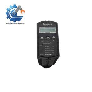
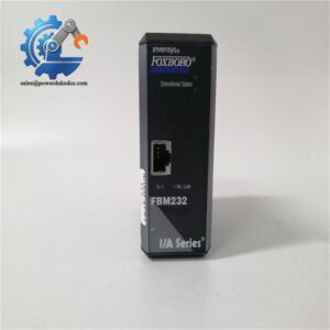
An analog input failure can be difficult to isolate because the symptom may appear in the transmitter, field wiring, termination assembly, or DCS input channel. The Foxboro AD202MW is associated in current inventory references with the FBM2XX4 analog input interface family for Foxboro I/A Series systems. Recent specialist listings describe the AD202MW as a multi-channel analog input module, with one current catalog identifying it as a 16-channel analog input module.
Published secondary specifications are not fully consistent, so procurement should not rely on a single listing for every electrical value. One current technical reference describes configurable 4–20 mA and voltage inputs, 16-bit conversion, galvanic isolation, 24 VDC nominal power, and approximately 2.5 W maximum consumption. Another catalog incorrectly describes AD202MW as a control processor. Because of that conflict, the exact FBM2XX4 association, channel count, revision, terminal assembly, and field signal type should be confirmed from the physical module and approved Foxboro documentation before installation.
Module 4: Application Scenarios & Field Realities
- On refinery pressure and flow loops, an analog input interface such as the AD202MW can sit between field transmitters and the Foxboro I/A Series control architecture, converting process measurements into values available to the control application. The important commissioning check is end-to-end scaling, not simply whether the module powers up.
- Where multiple 4–20 mA transmitters terminate in one DCS cabinet, channel-level troubleshooting should separate transmitter faults from input-card faults. Injecting a calibrated current directly at the termination point is often the fastest way to determine whether the problem follows the field loop or remains with the input channel.
- For mixed process instrumentation, current and voltage input capability has been reported for the AD202MW/FBM2XX4 listing, but the actual supported range and channel configuration must be verified against the installed hardware revision before connecting transmitters.
- During planned I/A Series maintenance, channel mapping deserves as much attention as the card itself. Record each transmitter tag, termination position, module channel, engineering range, and alarm limit before removing the existing assembly. A physically correct replacement with incorrect configuration can still produce misleading process values.
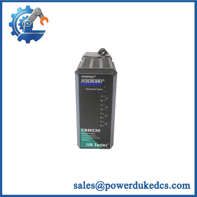
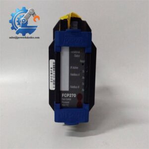
Foxboro AD202MW FBM2XX4
Module 5: Migration, Compatibility & Installation Traps
Replacement Matrix
| Replacement Status | Engineering Assessment |
|---|---|
| Drop-in Replacement | Yes, for a like-for-like / FBM2XX4 installation with matching I/A Series hardware revision, terminal assembly, signal type, and configured channel mapping. |
| Software Compatible | Generally yes for an exact hardware replacement, but the I/A Series configuration database, channel assignments, scaling, alarm settings, and installed firmware baseline must be preserved and checked. |
| Hardware Modification Required | Normally no for an exact replacement. Modification may be required when changing channel architecture, terminal hardware, signal type, or a different FBM family. |
⚠️ Field Traps: Watch Out
Confirm the exact channel count before placing the order. Current secondary sources are inconsistent: one catalog identifies FBM2XX4 as a 16-channel analog input module, while another describes the same model as a four-channel interface. The physical nameplate and controlled Foxboro documentation should settle the configuration.
Do not trust the “control processor” classification found on some supplier pages. is also incorrectly marketed online as an I/A Series control processor with Ethernet and 16 MB memory. Those specifications conflict with the separate analog-input references and should not be used as the engineering baseline.
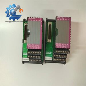
Match the termination assembly. Foxboro I/A Series field modules are installed within a specific carrier and termination architecture. Before replacement, verify the connected termination type, cable assembly, channel numbering, and field-signal wiring.
Bench-test current injection before reconnecting field devices. A calibrated 4–20 mA source can verify the complete input path without exposing the process to an uncontrolled instrumentation fault. Check zero, mid-scale, and full-scale values against the configured engineering range.
Module 6: Quality Assurance SOP
should be inspected as an analog signal-acquisition component, with channel-by-channel verification before shipment.
- OEM anti-counterfeit visual inspection: Verify Foxboro identification, marking, designation where present, PCB revision, connector geometry, terminal interface, and visible manufacturing markings.
- Part-number and traceability check: Record the complete designation, hardware revision, serial number, date code, and any associated FBM identification.
- Mechanical inspection: Examine the enclosure, backplane connector, terminal interface, retaining hardware, connector pins, and PCB for corrosion, contamination, bent contacts, cracks, or unauthorized repair.
- Power-on self-test (POST): Install the module in an appropriate Foxboro I/A Series test arrangement and verify normal startup and module diagnostic behavior.
- 24 VDC supply verification: Where supported by the controlled test fixture, apply the verified nominal supply and monitor current consumption for abnormal values.
- Analog-input channel test: Inject calibrated 4–20 mA signals into each available channel and verify correct channel identification, measurement, and scaling.
- Voltage-input test: Where the specific hardware revision supports voltage inputs, use calibrated 0–5 V and/or 0–10 V sources only after confirming the approved input configuration. Current secondary specifications report these ranges, but they should not be generalized across unidentified revisions.
- Accuracy verification: Compare measured values at low-scale, mid-scale, and high-scale points against the applicable Foxboro engineering tolerance.
- Isolation verification: Where galvanic isolation is part of the specified configuration, verify isolation between the field channels and system interface according to the approved laboratory procedure.
- Open-loop diagnostic test: Introduce a controlled open-circuit condition and verify the expected diagnostic response where the installed revision supports this function.
- Signal-range diagnostic test: Apply controlled out-of-range inputs and confirm that the configured diagnostic behavior is reported correctly.
- System recognition test: Verify that the Foxboro I/A Series controller or interface recognizes the installed module and assigns the expected channel addresses.
- Communication handshake verification: Confirm successful data transfer between the analog module and the I/A Series system. This should be tested through the actual module-to-system interface rather than treating the field input card as a standalone Ethernet device.
- Channel mapping verification: Compare every tested channel against the approved tag list, termination position, and configuration database.
- Extended-run test: Operate the module under representative channel loading and continuously monitor analog stability, diagnostic status, supply current, and abnormal temperature rise.
- Final QC record: Document exact part number, channel configuration, revision, supply measurements, channel-by-channel analog readings, diagnostic tests, isolation results, system recognition, extended-run observations, and packaging status.
Technical Identification Note: The supplied designation is difficult to normalize because publicly indexed secondary sources provide conflicting classifications. Current Foxboro inventory references associate with the analog input family, including a listing that identifies it as a 16-channel analog input module. Other pages incorrectly describe the same part number as a control processor. For procurement accuracy, the safest record is , with the physical module label, FBM designation, channel count, and hardware revision verified before shipment.



 Start Chat


