

Description
- Brand: GE Multilin
- Full Model Number: 350-E-P1-G1-H-E-E-N-P-SN-D
- System/Series Family: Multilin 350 Feeder Protection System
- Core Function: Numerical protection, control, metering, and monitoring for medium-voltage and high-voltage feeder applications
- Top 3 Hardcore Specs: 1 A phase-current input; 1 A ground-current input; 110–250 VDC / 110–230 VAC auxiliary supply
- Stock Status: New Surplus — exact hardware revision and option configuration to be confirmed before shipment
The GE Multilin 350-E-P1-G1-H-E-E-N-P-SN-D is a configured member of the Multilin 350 feeder protection relay family. GE’s 350 platform is intended for feeder protection and control, with configurable current inputs, protection functions, metering, communications, and control options. The exact order code matters because individual 350 units can have materially different hardware configurations.
For the P1/G1 configuration, available technical records identify 1 A three-phase phase-current inputs and 1 A standard ground-current input. Comparable 350-E P1/G1 configurations are specified for 110–250 VDC or 110–230 VAC, 50/60 Hz auxiliary power.
Module 3: Technical Product Introduction
A feeder relay replacement is not a simple matter of matching the front-panel model number. CT ratios, ground-current inputs, trip logic, auxiliary power, communications, and programmed protection elements all affect whether the replacement can return a feeder to service without engineering changes. The GE Multilin 350-E-P1-G1-H-E-E-N-P-SN-D belongs to the 350 feeder protection family and uses the P1/G1 1 A current-input configuration. The 350 platform provides numerical feeder protection, control, measurement, and monitoring functions.
The published configuration data for comparable P1/G1 units identifies three-phase 1 A phase-current inputs, 1 A ground-current input, and a wide-range auxiliary supply of 110–250 VDC / 110–230 VAC at 50/60 Hz. The final E-N-P-SN-D option sequence must still be verified against the physical relay and original documentation before shipment; do not assume that another 350-E relay with the same current ratings has identical I/O, control, communication, or protection options.
Module 4: Application Scenarios & Field Realities
- On a medium-voltage feeder with 1 A CT secondaries, the P1/G1 configuration is relevant because the relay’s current inputs are designed around the 1 A secondary system. Confirm the actual CT secondary rating before connecting the replacement.
- For feeder breaker protection, the relay can form part of the trip, alarm, measurement, and control chain. Preserve the existing protection settings and output logic rather than treating the replacement as a factory-default device.
- During a substation relay replacement, document every CT, VT, breaker-status, trip, close, alarm, and control connection before removing the original unit. The terminal arrangement and option code should be checked against the wiring diagram.
- When investigating nuisance feeder trips, download the existing event records and settings before replacement where possible. A new relay with default settings can behave correctly as hardware while still producing an incorrect protection response.
Module 5: Migration, Compatibility & Installation Traps
Replacement Matrix
| Replacement Type | 350-E-P1-G1-H-E-E-N-P-SN-D Assessment | Engineering Requirement |
|---|---|---|
| Drop-in Replacement | Potentially yes for an exact configuration match | Match complete order code, CT/ground inputs, power supply, I/O, communications, and hardware revision |
| Software Compatible | Yes, configuration-dependent | Transfer and verify protection settings, logic, metering, and communication parameters |
| Hardware Modification Required | Potentially for other 350 variants | Required if current-input, I/O, power, or communication configuration differs |
Field Trap 1 — 1 A versus 5 A CT inputs:
The P1 configuration is associated with 1 A phase-current inputs, while other 350 configurations use different CT ratings. Never connect a 5 A CT secondary to a relay configured for 1 A inputs simply because both units carry the 350 model designation.
Field Trap 2 — Auxiliary supply verification:
Comparable 350-E P1/G1 configurations are listed for 110–250 VDC / 110–230 VAC operation. Verify the actual auxiliary supply and relay nameplate before energization. A wide-range supply rating does not eliminate the need to check polarity, frequency, grounding, and terminal wiring.
Installation note: CT circuits require particular care. Follow the approved protection-maintenance procedure, isolate the feeder, and never leave an energized CT secondary open-circuited. Record the original relay settings, FlexLogic/control configuration, communication parameters, and terminal wiring before replacement.
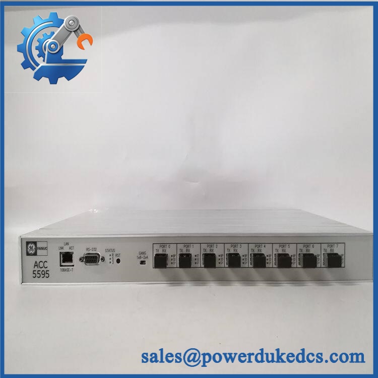
GE 350-E-P1-G1-H-E-E-N-P-SN-D
Module 6: Quality Assurance SOP
- OEM identification inspection — Verify the complete 350-E-P1-G1-H-E-E-N-P-SN-D order code, GE Multilin branding, serial number, firmware information, and hardware revision.
- Configuration-code inspection — Check each option segment against the physical relay and available configuration documentation. Do not release a unit based solely on the generic “350-E” designation.
- Physical inspection — Examine the faceplate, LCD, keypad, terminal blocks, communication ports, enclosure, mounting points, and accessible PCB areas for damage, corrosion, contamination, or previous repair.
- OEM anti-counterfeit visual inspection — Check GE Multilin labels, enclosure construction, terminal arrangement, PCB markings, connector geometry, and manufacturing identifiers against authenticated reference hardware.
- Power-on self-test (POST) — Apply the specified auxiliary supply in a controlled test environment and verify startup, display operation, diagnostic status, and self-test results.
- CT input verification — Using a calibrated relay test set, inject representative 1 A phase-current signals and verify phase measurement, scaling, frequency, and metering accuracy. Verify the ground-current channel separately.
- Protection-function verification — Test the protection elements required by the customer’s application, including applicable phase and ground overcurrent functions, timing characteristics, pickup values, and trip outputs.
- Digital I/O verification — Exercise configured binary inputs and outputs individually. Confirm pickup, dropout, contact state, and programmed logic against the approved test procedure.
- Communication handshake verification — Establish communication through the installed interface and verify representative data exchange using the customer’s approved protocol, address, and communication parameters.
- Event-record verification — Generate controlled protection events and confirm correct event capture, timestamps, target indications, and available disturbance records.
- Settings verification — Record and compare CT ratios, protection settings, output assignments, programmable logic, communication settings, and enabled functions against the customer’s approved configuration.
- Final traceability record — Photograph the complete nameplate and order code, document the physical condition, retain test results, and package the relay using ESD-safe and mechanically protective materials.
For GE 350-E-P1-G1-H-E-E-N-P-SN-D, the complete configuration code should remain the primary procurement reference. The P1/G1 combination is particularly important because it identifies the 1 A phase and ground-current configuration; other 350 variants may use different current ratings or option sets. Before installation on an energized protection system, match the relay’s complete order code, CT/VT requirements, auxiliary supply, I/O arrangement, firmware, and protection settings.











 Start Chat


