

Description
- Model: 531X301DCCAFG2
- Brand: General Electric (GE)
- Series: Mark V / 531X drive-control hardware
- Part Type: DCCA Main Drive Control Board
- Core Function: Performs drive-control processing and coordinates control logic, data handling, and communication functions within the associated GE drive/control architecture.
- Key Specs: Intel 80186 processor, nonvolatile EEPROM for configuration-related data, RAM/flash memory elements, serial and network communications reported by secondary technical records, and legacy Mark V architecture.
Product Introduction
A failed DCCA can leave a GE drive or associated control system unable to complete its normal processor startup sequence, even when the surrounding I/O and power hardware remain available. The 531X301DCCAFG2 is identified as a Main Drive Control board and is associated with GE’s Mark V control hardware. Secondary technical records describe an Intel 80186 processor and onboard memory used for software and control data.
This is a configuration-sensitive legacy processor card. The board has been reported in the field as a replacement candidate for 531X301DCCAGG2, but the change is not something to treat as a blind plug-in substitution. A field-engineering discussion documents a 531X301DCCAFG2 DCCA failure and a replacement using 531X301DCCAGG2, followed by a different Mark V startup state, illustrating why firmware, EEPROM contents, system configuration, and the complete control-core arrangement need to be checked during migration.
Core Technical Specifications
| Parameter | Value |
|---|---|
| Manufacturer | General Electric (GE) |
| Exact Part Number | 531X301DCCAFG2 |
| Functional Designation | DCCA |
| Product Description | Main Drive Control Card / Main Control Card |
| Product Family | GE Mark V / 531X series |
| Processor | Intel 80186, according to secondary technical records |
| Memory Architecture | RAM and flash memory reported; EEPROM used for configuration/adjustment data |
| Control Role | Drive control processing, control logic execution, signal/data handling |
| Communications | RS-485 and Ethernet reported by secondary technical records |
| Event / Trip Data | Secondary records describe trip/event logging capability in the associated control architecture |
| Alarm Time Resolution | Approximately 62 ms reported |
| User-Defined Event Resolution | Approximately 1 ms timestamp resolution reported |
| Input Power Reference | 125 VDC or 120/240 VAC reported by one commercial technical source; verify against the actual drive installation |
| Reported Operating Temperature | -25°C to +55°C in one commercial technical record |
| Reported Storage Temperature | -40°C to +85°C in one commercial technical record |
| Approximate Dimensions | 190 × 260 × 80 mm reported by one commercial listing |
| Approximate Weight | 2.5 kg reported by one commercial listing |
| Firmware | Board/system firmware stored in nonvolatile memory; exact revision must be verified from the installed unit |
The part-specific commercial evidence identifies 531X301DCCAFG2 as a Main Drive Control Board and lists an Intel 80186 processor, memory resources, communication interfaces, environmental figures, and physical measurements. These details are useful for procurement screening but should not be treated as a substitute for the original GE installation documentation.
One important point for asset managers: the 2.5 kg and 190 × 260 × 80 mm figures conflict with another listing that reports approximately 1.25 lb and 38 × 36 × 32 cm. Because the measurements are inconsistent, the physical unit should be weighed and measured before issuing export documents or freight quotations.
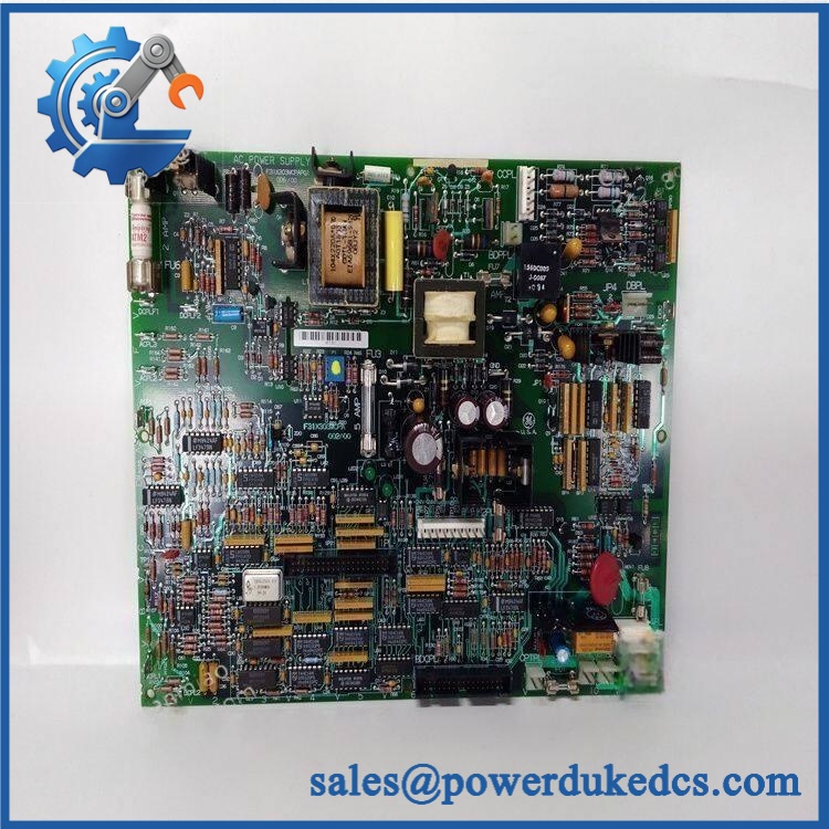
GE 531X301DCCAFG2
Application Scenarios & Pain Points
In a drive-control outage, a DCCA processor failure can present as a controller that does not boot normally, loses associated display functionality, or fails to reach the expected Mark V operating state. A field-engineering report specifically describes a failed 531X301DCCAFG2 that lost the display on an associated LCCB card and would not boot.
For legacy gas-turbine or industrial-drive installations, the DCCA board is part of the older Mark V control ecosystem, where processor cards, LAN cards, I/O boards, and terminal assemblies work together. GE spare-parts references identify the 531X301DCCA family alongside LCC communication and I/O hardware.
During migration planning, replacing an old DCCA with a newer revision can require more than hardware installation. A 2015 field discussion records the use of 531X301DCCAGG2 as a replacement for DCCAFG2 and reports the replacement unit remaining at Mark V status A4, making system initialization and memory/configuration handling important parts of the change procedure
At cabinet temperatures approaching 50°C or higher, thermal inspection should be included in troubleshooting. One secondary listing reports a -25°C to +55°C operating range, so actual cabinet temperature should be measured rather than estimated from room conditions.
🚨 Common Error Codes & Diagnostic Symptoms
The DCCA is a processor/control board, and the Mark V architecture uses controller status codes and system-state information rather than a single modern module diagnostic table.
Symptom/Code: Mark V remains at A4 after DCCA replacement → Diagnosis: A replacement DCCA may not have the expected EEPROM contents, firmware, or configuration for the installed control core. A field report documents this exact A4 condition after replacing DCCAFG2 with DCCAGG2. → Action: Verify EEPROM devices, firmware, control-core configuration, and the associated I/O state before replacing the board again.
Symptom/Code: DCCA does not boot / associated LCC display lost → Diagnosis: Possible processor startup failure, damaged nonvolatile memory, power instability, or board-level hardware failure. A field report specifically links a failed DCCAFG2 with loss of LCCB display and failure to boot. → Action: Verify control power and associated interfaces; replace the DCCA when the fault is confirmed at the board level.
Symptom/Code: Unexpected control-core status or unstable restart → Diagnosis: Possible firmware/configuration mismatch, memory corruption, or processor-board fault. → Action: Capture the existing firmware and EEPROM configuration before replacement, then compare the replacement against the approved Mark V baseline.
🚨 Cross-Reference & Lifecycle Migration
Cross-Reference
The most significant replacement relationship identified in available records is:
531X301DCCAFG2 → 531X301DCCAGG2
A commercial GE spare-parts reference explicitly states that 531X301DCCAGG2 supersedes 531X301DCCAFG2.
However, the replacement should not be described as a universal drop-in change. A field-engineering report documents a DCCAFG2-to-DCCAGG2 replacement that left the <T> core at A4, demonstrating that the migration can require system-specific initialization or memory/configuration work.
Firmware Requirement
Firmware and nonvolatile memory must be checked.
The DCCA architecture contains processor firmware and EEPROM-based configuration data. One technical listing explicitly notes that new software can be downloaded to EEPROM and that a board-mounted pushbutton can restart the processor after software loading.
Before replacement, capture the existing:
- Firmware/software revision
- EEPROM device configuration
- Control-core configuration
- I/O state
- LCC/LCCB relationship
- Network and serial settings where applicable
Do not erase or overwrite the original EEPROM content before it has been documented.
Lifecycle Status
Status: Obsolete / Legacy
Current commercial references list the 531X301DCCAFG2 as obsolete Mark V drive-control hardware, while current secondary spare-parts catalogs continue to list it as a service item.
For buffer-stock planning, this part deserves controlled inventory treatment. Keep at least the exact DCC revision and its related configuration records together; a physically similar DCCA board without the correct memory or revision can create a longer outage rather than solving one.
Field Engineer’s Tech Notes
Warning 1 — Preserve the EEPROM configuration before removing the old DCCA.
The DCCA’s nonvolatile devices can contain software and control data required by the installed application. Do not discard or swap EEPROM devices casually. A replacement board with blank, wrong, or mismatched memory can power up while still failing to reach the expected control state.
Warning 2 — Do not treat A4 as proof that the replacement card is defective.
After a DCCA change, the status shown by the Mark V core can reflect configuration or initialization issues rather than a failed PCB. Check the control-core I/O states and associated LCC/IOMA conditions before ordering another board (the field case involving DCCAGG2 is a useful reminder).
Strict QA & Testing SOP
Step 1 — Part identity check
Verify 531X301DCCAFG2 from the physical label and board marking. Record every revision, assembly identifier, serial number, and EEPROM identifier visible on the board.
Step 2 — PCB inspection
Examine the board for corrosion, burned components, cracked solder joints, damaged connectors, bent pins, contamination, and unauthorized repair work.
Step 3 — Memory inspection
Inspect the EEPROM devices and sockets carefully. Record device positions and markings before applying power.
Step 4 — Power-rail pre-check
Before live testing, verify the approved board/chassis supply conditions. Do not apply the 125 VDC or 120/240 VAC figures from a secondary listing directly to the exposed PCB without confirming the actual Mark V cabinet interface.
Step 5 — Controlled startup
Install the DCCA in a compatible Mark V test environment and observe processor startup, board status, associated display behavior, and control-core initialization.
Step 6 — Firmware verification
Record the firmware revision and compare it with the approved baseline for the target Mark V system. When EEPROM-based software is involved, confirm the programmed devices before system testing.
Step 7 — Control-state testing
Check expected Mark V operating states and verify that the controller progresses normally through initialization rather than remaining at an abnormal status.
Step 8 — Communication testing
Verify applicable RS-485 and network communication paths where the test system supports them. Confirm that the DCCA can communicate with the associated controller and interface boards.
Step 9 — Event and diagnostic verification
Where supported by the test setup, verify event logging, alarm capture, and timing behavior. Secondary records report approximately 62 ms alarm resolution and 1 ms user-event timestamp resolution.
Step 10 — Extended powered observation
Run the board under a controlled operating period and monitor for restart events, communication loss, abnormal heating, or intermittent control-state changes.
Step 11 — Documentation
Record part number, revision, EEPROM data, firmware, test results, photographs, and inspector information.
Step 12 — ESD-safe packaging
After testing, place the board in an ESD shielding bag, protect all connectors and exposed components, and use rigid cushioning to prevent PCB flex during transport.
Test videos are available for applicable tested units and compatible Mark V test configurations.
Buyer’s FAQ
Can I hot-swap the 531X301DCCAFG2?
Do not assume that this DCCA processor board is hot-swappable. It is part of a legacy Mark V control core, and removing it can affect processor state, stored configuration, communications, and associated control hardware. Use the approved Mark V maintenance procedure and isolate the relevant power before replacement.
How do I verify a New Original 531X301DCCAFG2?
Request photographs of the actual board, including the GE part number, revision, processor area, EEPROM devices, connectors, and packaging. For a legacy DCCA, the board’s memory devices and revision information are particularly important because a visually similar replacement may not contain the configuration expected by the installed control system.
Is 531X301DCCAGG2 a replacement for 531X301DCCAFG2?
Available spare-parts references identify 531X301DCCAGG2 as a superseding part for DCCAFG2. Field evidence, however, shows that a replacement can require system-specific configuration or initialization, so it should not be treated as a simple unrestricted hardware swap.
What warranty should I expect?
Warranty depends on the supplier’s written terms and the condition category of the board. For obsolete Mark V hardware, obtain the warranty period, test scope, memory/EEPROM status, actual serial information, and return conditions before purchase. A third-party warranty should not be described as a GE factory warranty unless separately documented.











 Start Chat


