

Description
- Model: 531X304IBDARG1
- Brand: General Electric (GE)
- Series: 531X / AC2000 drive-control hardware
- Part Type: Base Drive Card / Base Driver PCB
- Core Function: Provides the drive-side base control and signal-interface circuitry required by compatible GE AC2000 drive systems.
- Key Specs: Legacy discrete-electronics architecture; 3 crystal-oscillator sections, 5 male board-interface connectors, multiple jumper positions, transformers, heat sinks, transistors, capacitors, resistors, and diodes. The part is listed as an AC2000 Base Drive Card in legacy GE equipment records.
Product Introduction
When an older GE drive has valid control commands but the downstream drive stage does not respond correctly, the base-drive interface becomes one of the hardware areas worth checking. 531X304IBDARG1 is identified as a GE PC Base Drive Card, with legacy equipment catalogs also listing it as an AC2000 Base Drive Card. Its job is tied to drive control and signal conditioning rather than general-purpose PLC I/O.
This is a hardware-configured board. Published inspection data describe three crystal oscillators, five male ports, six metal brackets, jumper circuitry, transformers, heat sinks, transistors, resistor networks, capacitors, and diodes. Such construction is typical of an older drive platform where physical board configuration and component condition matter during maintenance (record the original jumper state before removing the board).
Core Technical Specifications
| Parameter | Value |
|---|---|
| Manufacturer | General Electric (GE) |
| Part Number | 531X304IBDARG1 |
| Board Designation | IBDARG1 |
| Product Type | PC Base Drive Card / Base Driver Card |
| Product Family | GE 531X Boards |
| Associated System | GE AC2000 drive-control equipment |
| Related Board Identifier | F31X304IBDAMG1 is documented with 531X304IBDARG1 as a secondary identification |
| Crystal Oscillators | 3 reported |
| Board Interface Connectors | 5 male ports reported |
| Transformers | 3 repeated circuit sections reported on related board documentation |
| Heat Sinks | Multiple heat sinks; six reported on the related F31X304IBDAMG1 assembly |
| Jumper Circuits | Multiple configurable jumper positions |
| Transistors | Multiple discrete transistor devices |
| Passive Components | Resistors, resistor arrays, capacitors, diodes |
| Mechanical Mounting | Multiple mounting holes/brackets |
| Processor | No independent CPU specification verified |
| Application Memory | No independently documented user memory |
| Firmware | No standalone firmware package verified for the board |
| Ethernet | No independent Ethernet interface verified |
| Fieldbus | No independent fieldbus interface verified |
| Board-Level Supply | Through the associated GE drive architecture; exact board input not verified |
| Operating Temperature | Exact OEM board-level value not verified |
| Storage Temperature | Exact OEM board-level value not verified |
| Exact Dimensions | OEM dimensional drawing not verified |
| Exact Net Weight | OEM net weight not verified |
| Lifecycle | Legacy / obsolete service hardware |
The exact part is consistently identified as a base-drive board, while one technical reference for the corresponding F31X assembly identifies six heat sinks, three transistors, six red LEDs, three 8-pin vertical headers, an additional two-pin header, and one top-edge cable connector. Those details are useful for physical identification but should not be assumed to describe every hardware revision of IBDARG1.
Published commercial records also list 531X304IBDARG1 among GE AC2000 base-drive cards, confirming its place in the legacy drive-control inventory.
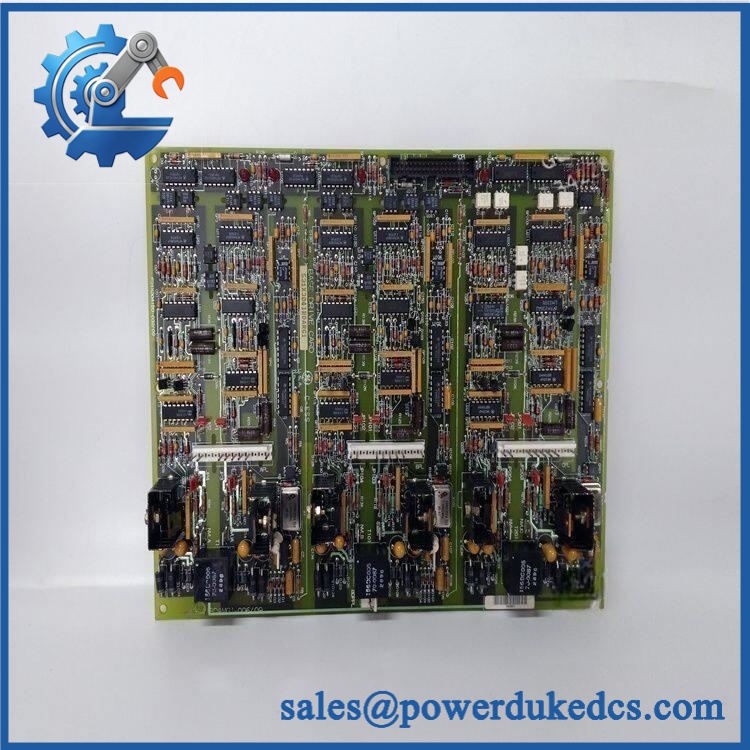
GE 531X304IBDARG1
Application Scenarios & Pain Points
Micro-case — drive output does not follow the control command. When the controller issues the expected command but the associated drive stage shows abnormal or missing response, technicians typically work through the control signal path, power stage, and base-drive circuitry. IBDARG1 is part of that drive-side control chain.
Within GE installations, the board is used as a Base Drive Card, so it should not be confused with the separate NTB terminal boards, MCP power boards, or LCC communication boards found in the same 531X ecosystem. Legacy equipment catalogs list those assemblies as separate functional items.
During a legacy migration, exact board revision becomes important. A current parts reference states 531X304IBDARG1/EX — USE 531X304IBDASG1/EX, while other records list IBDASG1 as a later base-drive card. This is useful cross-reference information, but it does not establish universal drop-in compatibility for every cabinet.
At cabinet temperatures around 50°C, inspect heat-sink hardware, airflow, connectors, and component discoloration carefully. A reliable OEM operating limit for the individual IBDARG1 board was not established from the reviewed public records, so the installed GE drive specification should control the environmental assessment.
🚨 Common Error Codes & Diagnostic Symptoms
This PCB does not have a modern standalone diagnostic-code system. Troubleshooting is generally performed from the associated GE drive’s operating behavior, diagnostic measurements, status indicators, and control signals.
Symptom/Code: Drive command present but base-drive response absent → Diagnosis: Possible failure in timing, signal-conditioning, transistor, transformer, or board-interface circuitry; an external inhibit or power-stage fault can produce similar symptoms. → Action: Verify upstream control signals and drive power conditions first; replace the IBDARG1 after the fault is localized to the board.
Symptom/Code: Unstable or intermittent drive control → Diagnosis: Possible marginal jumper setting, loose connector, degraded solder joint, oscillator problem, or component deterioration. → Action: Inspect the board configuration and connectors, then perform controlled board testing before replacement.
Symptom/Code: Fault appears after thermal cycling → Diagnosis: Possible temperature-sensitive solder-joint, connector, semiconductor, or passive-component degradation. → Action: Compare the fault under controlled thermal conditions and inspect the board’s heat-transfer areas before declaring the entire assembly defective.
🚨 Cross-Reference & Lifecycle Migration
Cross-Reference
The most significant replacement relationship identified for this board is:
531X304IBDARG1 → 531X304IBDASG1
A legacy GE parts reference explicitly states 531X304IBDARG1/EX — USE 531X304IBDASG1/EX, and separate equipment catalogs identify IBDASG1 as an Base Drive Card.
Another related identifier is F31X304IBDAMG1, for which technical records specify 531X304IBDARG1 as a secondary board identification number. This is useful when reconciling older GE documentation or physical board markings.
Before approving a substitute, compare:
- Complete part number and suffix
- Board revision
- Jumper configuration
- Connector arrangement
- Transformer and heat-sink layout
- Host drive model
- Cabinet wiring
- Approved GE replacement documentation
Firmware Requirement
No conventional firmware flashing has been verified for IBDARG1 itself.
The published hardware descriptions focus on discrete circuitry, transformers, oscillators, jumpers, transistors, resistors, capacitors, diodes, and interface connectors.
Software or configuration requirements, where applicable, belong to the associated drive-control hardware rather than the passive or discrete base-drive PCB itself.
Lifecycle Status
Status: Legacy / Obsolete
Current legacy inventory references identify 531X304IBDARG1 as an obsolete service item and provide 531X304IBDASG1 as a later replacement reference in one parts-control database.
For buffer-stock planning, preserve the exact revision and its known jumper configuration. Grouping every 531X304 board under a generic “base drive card” inventory code can result in an incorrect board being issued during an outage.
Field Engineer’s Tech Notes
Warning 1 — Photograph the jumpers before extraction.
The board contains multiple jumper positions that form part of its electrical configuration. A replacement can look identical and still require a different setting for the target drive. Record each position before disassembly and compare it with the approved drawing.
Warning 2 — Do not apply guessed voltage directly to the PCB.
Commercial listings do not establish a sufficiently reliable standalone board-supply specification for . Use the actual schematic or approved service fixture to identify the correct test points. This avoids damaging a board that was simply tested with the wrong supply arrangement.
Strict QA & Testing SOP
Step 1 — Identity check
Confirm 531X304IBDARG1 from the actual board marking. Record all secondary numbers, revision codes, serial/date information, and any F31X identification.
Step 2 — Mechanical inspection
Inspect mounting holes, brackets, board slots, standoffs, connector housings, transformers, and heat sinks for damage or deformation.
Step 3 — Jumper documentation
Photograph every jumper position before any electrical work. Record the configuration in the QA file.
Step 4 — Connector inspection
Check all reported interface connectors for bent pins, oxidation, contamination, cracked housings, and damaged solder joints. The exact board is reported to have five male interface ports.
Step 5 — Component inspection
Inspect oscillators, transformers, transistors, capacitors, diodes, resistor networks, and heat sinks for abnormal discoloration or physical damage.
Step 6 — Passive electrical checks
Use the approved GE schematic to perform resistance, continuity, and component-level checks. Avoid arbitrary acceptance limits when the original service documentation is available.
Step 7 — Controlled power test
Install the board in a compatible test environment. Verify the correct supply arrangement from the test fixture before energization.
Step 8 — Timing/interface verification
Check the applicable timing and base-drive interface signals under controlled conditions. Confirm stable behavior across repeated operating cycles.
Step 9 — Drive-level functional test
Where a compatible test rig exists, verify the board in the complete control path and confirm expected drive response without connecting an uncontrolled production load.
Step 10 — Thermal observation
Monitor the board during extended operation for abnormal heat concentration around regulators, transformers, transistors, connectors, or heat sinks.
Step 11 — Documentation
Record part number, revision, jumper positions, measured values, test equipment, photographs, and final QA status.
Step 12 — ESD-safe packaging
After testing, place the board in ESD shielding material and protect the connectors, heat sinks, and exposed components against impact and moisture.
Test videos are available for applicable units tested on compatible GE drive hardware.
Buyer’s FAQ
Can I hot-swap the 531X304IBDARG1?
Do not assume hot-swapping is permitted. This is a drive-control PCB associated with the power-electronics architecture. Follow the approved GE maintenance procedure, isolate the drive, and verify zero energy before removing the board.
How do I verify a New Original 531X304IBDARG1?
Request photographs of the actual PCB, including the GE part number, secondary markings, jumper configuration, connector arrangement, transformers, heat sinks, and board condition. For legacy 531X hardware, these physical details provide useful evidence of identity.
Is 531X304IBDASG1 a replacement for ?
A legacy GE parts database explicitly identifies 531X304IBDASG1/EX as the replacement reference for 531X304IBDARG1/EX. Engineering should still verify the target cabinet, jumper arrangement, connector layout, and application before treating it as a direct replacement.
What warranty should I expect?
Warranty depends on the supplier’s written commercial terms and the unit’s condition category. For discontinued drive-control hardware, request the warranty period, functional-test coverage, actual board photographs, revision information, and return conditions before purchase. A third-party warranty should not be described as a GE factory warranty unless separately documented.











 Start Chat


