

Description
- Model: 531X305NTBANG1
- Brand: General Electric (GE)
- Series: GE 531X
- Part Type: NTB/3TB Terminal Board
- Core Function: Provides field-level signal termination and interface circuitry for compatible GE drive and excitation-control equipment.
- Key Specs: Regulated 5 VDC and 15 VDC outputs; unregulated 24 VDC and 125 VAC supply outputs; jumper-selectable 5 V/15 V encoder supply; 7 relays; low-level analog I/O; multiple terminal strips; passive interface circuitry.
Product Introduction
The GE 531X305NTBANG1 is an NTB/3TB terminal board used within legacy GE drive and exciter cabinets. Its role is primarily at the field-interface level: external signal wiring, relay control, analog signal handling, encoder connections, and auxiliary power distribution all terminate through this board. Industrial technical records specifically associate the assembly with GE drive systems and EX2000 excitation equipment.
For a maintenance replacement, the jumper state and terminal wiring matter just as much as the catalog number. The board contains regulated and unregulated supply circuits, seven relay outputs, analog scaling components, encoder circuitry, and numerous terminal positions. A replacement that has the wrong configuration can appear physically correct while producing incorrect field behavior (photograph the original board before extraction).
Core Technical Specifications
| Parameter | Value |
|---|---|
| Manufacturer | General Electric (GE) |
| Part Number | 531X305NTBANG1 |
| Alternate Identification | F31X305NTBANG1 |
| Product Family | GE 531X |
| Product Type | NTB/3TB Terminal Board |
| Application | GE drive and excitation systems |
| Related Equipment | EX2000 excitation systems; AC/DC2000 drive equipment is also reported |
| Interface Type | Passive field-level interface circuitry |
| Regulated Power Outputs | 5 VDC, 15 VDC |
| Unregulated Power Outputs | 24 VDC, 125 VAC |
| Encoder Supply | 5 V or 15 V |
| Encoder Configuration | Onboard jumper selection |
| Relay Quantity | 7 |
| Relay Type | Form A or Form C, application-dependent |
| Relay Contact Rating | 120 VAC reported |
| Analog I/O | Low-level analog signal interface |
| Analog Scaling | 4 potentiometers reported |
| Terminal Strips | 6 total |
| Screw-Terminal Arrangement | 2 × 24-position, 2 × 21-position, 2 × 3-position reported |
| Communication Interface | RS-232C / RS-422 related circuitry reported |
| Processor | No independent application processor established |
| Firmware | No standalone firmware identified |
| Application Memory | None established |
| Ethernet | No independent Ethernet interface established |
| Approximate Weight | About 1 lb / 0.45 kg reported by one technical source |
| Exact Dimensions | Not reliably established from OEM documentation |
| Exact Operating Temperature | Not reliably established for the individual board |
| Lifecycle | Legacy / discontinued |
Technical references consistently identify the unit as a 531X NTB/3TB terminal board with six terminal strips, seven relays, four potentiometers, jumper circuitry, and encoder support.
The board is also described as containing regulated 5 VDC and 15 VDC, unregulated 24 VDC and 125 VAC, seven relay circuits, and jumper-configurable encoder voltage.
Because the exact mechanical drawing was not established from the reviewed primary technical material, dimensions and shipping weight should be measured from the physical asset before export documentation is finalized.
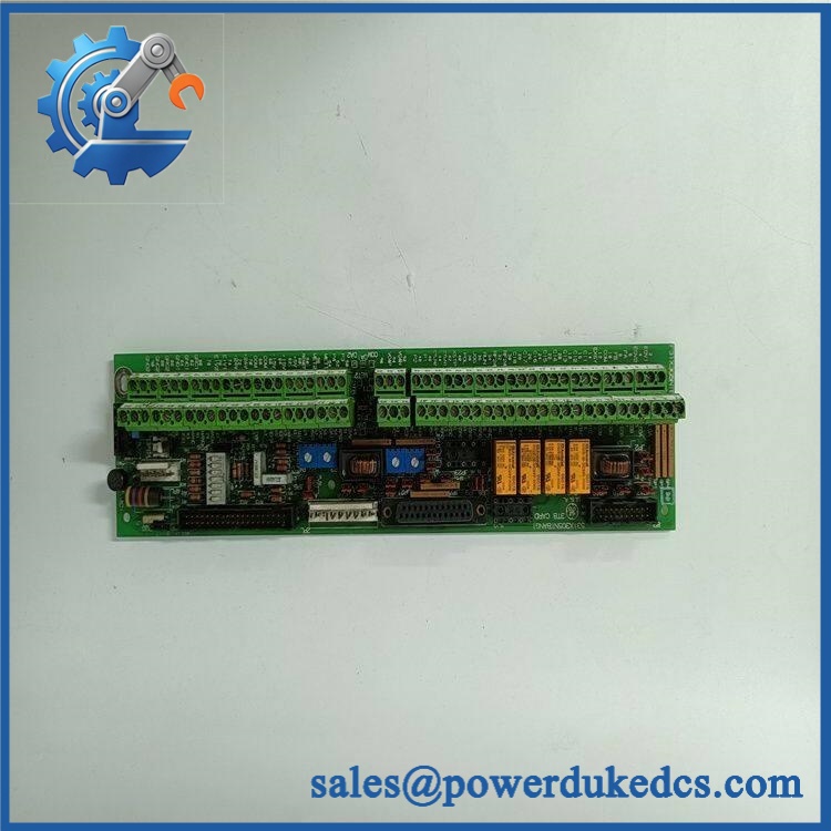
GE 531X305NTBANG1
Application Scenarios & Pain Points
Micro-case — several auxiliary functions fail together. When encoder feedback, relay status, and analog signals all become abnormal at approximately the same time, the common terminal interface deserves inspection. A shared supply or connector problem can affect several external circuits simultaneously.
Within GE AC/DC2000 drive cabinets, the NTB/3TB assembly provides the external interface for low-level signals and auxiliary connections. This makes terminal integrity important during both preventive maintenance and outage replacement work.
For EX2000 excitation equipment, the board is associated with external signal-level inputs and outputs, encoder circuits, relay functions, and power-distribution paths. The exact cabinet application should still be checked against the original wiring diagram before approving a replacement.
At cabinets reaching 50°C+, inspect terminals, relays, connectors, and power-supply sections for heat discoloration or loose connections. A verified board-level operating limit was not established in the reviewed records, so the host system’s environmental specification should control the engineering decision.
🚨 Common Error Codes & Diagnostic Symptoms
This terminal board is not a firmware-based controller, so there is no independent standard numeric fault-code table. Diagnosis normally relies on field measurements and the associated GE drive or exciter diagnostics.
Symptom/Code: 5 VDC or 15 VDC auxiliary supply missing → Diagnosis: Possible regulator failure, external short, overloaded connected device, or upstream supply problem. → Action: Isolate external loads and verify the supply path; replace the terminal board after the internal fault is confirmed.
Symptom/Code: Encoder feedback unstable or absent → Diagnosis: Incorrect 5 V/15 V jumper position, damaged encoder wiring, connector degradation, or internal interface failure. → Action: Verify encoder supply selection and differential signal wiring before replacing the board.
Symptom/Code: Multiple relay or analog functions fail at once → Diagnosis: Possible common power, connector, terminal, or board-interface fault. → Action: Check shared circuits first, then perform board-level testing and replace the NTB/3TB assembly when the fault follows the board.
🚨 Cross-Reference & Lifecycle Migration
Cross-Reference
The principal alternate identification is:
531X305NTBANG1 ↔ F31X305NTBANG1
A technical reference explicitly states that F31X305NTBANG1 has 531X305NTBANG1 as an alternate number and describes the board as an NTB/3TB terminal assembly used in drive/exciter applications.
Commercial records also identify 531X305NTBANG1/EX as an ACDC2000 terminal board. That item is currently marked discontinued.
These relationships should be treated as identification references rather than unrestricted substitution statements. Before approving a replacement, verify:
- Complete board number and suffix
- Jumper positions
- Terminal-strip arrangement
- Encoder supply requirement
- Relay configuration
- Analog scaling configuration
- Host drive or exciter model
- Cabinet wiring
Firmware Requirement
No firmware flashing is required for the terminal board itself.
The reviewed technical descriptions characterize this assembly as interface hardware containing power-supply circuits, relays, analog circuitry, encoder interfaces, potentiometers, connectors, and terminal strips rather than as a software-programmable controller.
Lifecycle Status
Status: Legacy / Discontinued
The GE 531X305NTBANG1/EX is currently listed as discontinued in an AC/DC2000 product record.
For buffer-stock management, store the exact board number and known application together. Record the jumper configuration as part of the asset file; otherwise, an electrically suitable-looking board may still require field reconfiguration before use.
Field Engineer’s Tech Notes
Warning 1 — Check the encoder jumper before energization.
The board supports 5 V and 15 V encoder configurations through onboard jumpers. Do not assume the factory position matches your cabinet. Photograph every jumper and compare the setting with the original schematic before applying encoder power.
Warning 2 — Treat the terminal strips as mixed-voltage interfaces.
This board carries regulated low-voltage supplies, unregulated outputs, relay circuits, analog signals, and encoder wiring. Never identify a terminal by physical location alone. Use the cabinet drawing and verify the circuit before placing a meter probe on an unfamiliar point (this is especially important on old AC2000/EX2000 cabinets).
Strict QA & Testing SOP
Step 1 — Identity verification
Confirm 531X305NTBANG1 on the physical board and record any F31X alternate marking, revision, serial number, and date/lot code.
Step 2 — Mechanical inspection
Inspect the PCB, mounting holes, terminal strips, relay housings, connectors, potentiometers, and hardware for cracking, corrosion, contamination, or deformation.
Step 3 — Jumper documentation
Photograph every jumper position before testing. Record the encoder-voltage configuration and any other selectable settings.
Step 4 — Terminal inspection
Check all six terminal strips for damaged threads, loose hardware, corrosion, insulation damage, and heat discoloration. The published layout includes two 24-position strips, two 21-position strips, and two 3-position strips.
Step 5 — Relay verification
Inspect the seven relays for physical damage and discoloration. Where the approved procedure allows, verify relay actuation and contact-state transitions.
Step 6 — Power-output test
Using a compatible test arrangement, verify the applicable 5 VDC and 15 VDC regulated outputs and the documented unregulated supply circuits. Do not apply an arbitrary voltage to a terminal without reference to the GE schematic.
Step 7 — Encoder interface test
Set the board to the required encoder voltage and test the interface with an approved signal simulator or known-good encoder.
Step 8 — Analog interface test
Check applicable low-level analog paths and scaling potentiometer behavior using calibrated instrumentation.
Step 9 — Drive/exciter functional test
Where a compatible GE AC2000 or EX2000 test setup is available, verify representative relay, encoder, analog, and power-interface functions.
Step 10 — Extended observation
Monitor the board for intermittent signal loss, relay instability, abnormal heating, or supply drift during an extended controlled test.
Step 11 — Documentation
Record part number, jumper positions, measured supply values, relay test results, analog measurements, photographs, and inspection status.
Step 12 — ESD-safe packaging
After testing, place the board in ESD shielding material and protect the terminal strips, relays, potentiometers, and connectors against impact and moisture.
Test videos are available for applicable units tested on compatible GE drive or excitation equipment.
Buyer’s FAQ
Can I hot-swap the 531X305NTBANG1?
Do not assume hot-swapping is permitted. The board carries power, relay, analog, and encoder circuits and can be connected to hazardous-energy sources within the drive or exciter cabinet. Follow the approved GE maintenance procedure and isolate the applicable circuits before removal.
How do I verify a New Original 531X305NTBANG1?
Request photographs of the actual PCB, including the complete part number, secondary markings, jumper configuration, six terminal strips, seven relays, and overall board condition. For legacy hardware, those physical details are important for confirming the exact assembly rather than relying on a generic catalog photograph.
What HS tariff code should be used?
There is no single universal tariff code that should be assigned from the model number alone. The item is a terminal/interface board for industrial drive and excitation equipment, and the final national tariff classification depends on the importing country’s tariff schedule.
For customs documentation, describe the product by its actual function and have the final HS/HTS classification confirmed by the customs broker.
Does the board include the latest firmware?
No. The 531X305NTBANG1 is a hardware terminal/interface board and is not identified as a firmware-managed processor module. Its behavior depends on its hardware circuitry, jumper configuration, terminal wiring, and the connected GE drive or exciter control system.
What warranty should I expect?
Warranty depends on the supplier’s written terms and the unit’s condition category. For discontinued legacy hardware, obtain the warranty period, functional-test scope, actual-board photographs, revision information, and return conditions before purchase. A third-party warranty should not be represented as a GE factory warranty unless separately documented.











 Start Chat


